
Specifications

Installation and Operation Manual Appendix A Pinouts
ASMi-52CQ Ver. 2.12 LRSI-F-21 and LRSI-F-29 Connections A-3
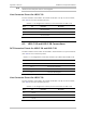
A.3 LRSI-F-21 and LRSI-F-29 Connections
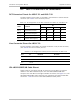
DCE Connector Pinout for LRSI-F-21 and LRSI-F-29
The DCE interface of the LRSI-F-21 and LRSI-F-29 terminate in a DB-25 female
connector (see
Table
A-5 for connector pinout).
Table
A-5. Pin Assignment of the DCE Connector for LRSI-F-21 and LRSI-F-29
Name Function
Pin
CH-1 CH-2 CH-3 CH-4
RX (+) Receive Data Positive 24 21 18 15
RX (-) Receive Data Negative 11 9 6 3
TX (+) Transmit Data Positive 23 20 17 14
TX (-) Transmit Data Negative 12 8 5 2
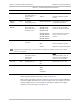
Line Connector Pinout for LRSI-F-29
The line interface of the LRSI-F-29 module terminates in a RJ-45 line connector,
(see
Table B-6
for the connector pinout).
Table
A-6. Pin Assignment of the RJ-45 Line Connector for LRSI-F-29
Pins ID
Function
Direction
1, 2 Line A
3 – Not connected –
4, 5 Line B
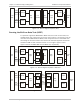
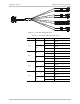
CBL-LRSI21/DB25/UB Cable Pinout
Splitter cable for connecting the DB-25 connector of the LRSI-F-21 interface
module to four BNC unbalanced ports. The CBL-LRSI21/DB25/UB/M cable
comprises one male DB-25 and eight male BNC connectors (see
Figure
A-1). The
CBL-LRSI21/DB25/UB/F cable comprises one male DB-25 and eight female BNC
connectors .
Table
A-7 lists the CBL-LRSI21/DB25/UB cable pinout.