
Specifications


Installation and Operation Manual Appendix B Parameter List
ASMi-52CQ Ver. 2.12 Displaying Modem Status B-11
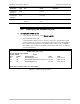
B.3 Displaying Modem Status
³ To display modem status:
1. From the Main menu, select Modem Status.
2. Select the ASMi-52CQ slot.
The Modem Status screen appears (see
Figure
B-5
). The Modem Status
screen provides information on the system interfaces and front panel LED
status.
Table
B-6
explains the parameters on this screen.
3. To display the second page of parameters, move the cursor to NEXT
PARAMETERS field by pressing <Tab>, select YES by pressing <F> or <B>, and
pressing <Tab> again.
The second page of the Modem Status screen appears (see
Figure
B-6
).
Table
B-7
explains the parameters on this screen.
MODEM STATUS
MODEM NAME: ASMi-52CQ
DEFINE MODEM PORT NUMBER: 1
SELECT MODEM : MODEM 1 LOCAL REMOTE MODEM : NULL
INTERFACE MODULE : LRSI-F-20 REMOTE SLOT : N/A
MODEM PORT : E1 REMOTE MODEM LINE CONNECTOR:TERM.BLOCK
SW VERSION : 0.2E1 REMOTE MODEM FRONT PANEL : N/A
HW VERSION : 00 .00 HW PANEL VERSION : 03
LED STATUS: 1)RTS: OFF 2)DCD: OFF 3)TEST: OFF 4)ERR: ON
5)ELE-LOW: ON 6)ELE-AIS: OFF 7)OPT-LOW: OFF 8)OPT-
AIS: OFF
LINK QUALITY : N/A PS PHANTOM STATUS : N/A
BPV ERROR : N/A CHASSIS : N/A
FIBER OPTIC ERROR : N/A WAVE LENGTH : 850
LINE UTILITY : 01 %
BERT RUN TIME : 0 BERT ERR SECONDS : 0
BERT SYNC LOSS : 0 BERT PRE FEC : 0
BERT POST FEC : 0
NEXT PARAMETERS : NO
Figure
B-5. Modem Status Screen
Bolded rows in
Figure
B-5
indicate parameters applicable to ASMi-52CQ.
Non-bolded parameters listed on a screen to other modems installed in the
LRS-24 chassis.
The Modem Status parameters and values are explained in
Table
B-6
.