Installation and Operation Manual ASMi-52L 2/4-Wire SHDSL Modem Version 1.
ASMi-52L 2/4-Wire SHDSL Modem Installation and Operation Manual Notice This manual contains information that is proprietary to RAD Data Communications Ltd. ("RAD"). No part of this publication may be reproduced in any form whatsoever without prior written approval by RAD Data Communications.
Limited Warranty RAD warrants to DISTRIBUTOR that the hardware in the ASMi-52L to be delivered hereunder shall be free of defects in material and workmanship under normal use and service for a period of twelve (12) months following the date of shipment to DISTRIBUTOR.
General Safety Instructions The following instructions serve as a general guide for the safe installation and operation of telecommunications products. Additional instructions, if applicable, are included inside the manual. Safety Symbols Warning This symbol may appear on the equipment or in the text. It indicates potential safety hazards regarding product operation or maintenance to operator or service personnel.
Handling Energized Products General Safety Practices Do not touch or tamper with the power supply when the power cord is connected. Line voltages may be present inside certain products even when the power switch (if installed) is in the OFF position or a fuse is blown. For DC-powered products, although the voltages levels are usually not hazardous, energy hazards may still exist.
Connection of Data and Telecommunications Cables Data and telecommunication interfaces are classified according to their safety status. The following table lists the status of several standard interfaces. If the status of a given port differs from the standard one, a notice will be given in the manual. Ports Safety Status V.11, V.28, V.35, V.36, RS-530, X.
Caution Attention To reduce the risk of fire, use only No. 26 AWG or larger telecommunication line cords. Pour réduire les risques s’incendie, utiliser seulement des conducteurs de télécommunications 26 AWG ou de section supérieure. Some ports are suitable for connection to intra-building or non-exposed wiring or cabling only. In such cases, a notice will be given in the installation instructions. Do not attempt to tamper with any carrier-provided equipment or connection hardware.
Canadian Emission Requirements This Class A digital apparatus meets all the requirements of the Canadian Interference-Causing Equipment Regulation. Cet appareil numérique de la classe A respecte toutes les exigences du Règlement sur le matériel brouilleur du Canada. Warning per EN 55022 (CISPR-22) Warning This is a class A product. In a domestic environment, this product may cause radio interference, in which case the user will be required to take adequate measures.
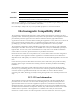
Declaration of Conformity Manufacturer's Name: RAD Data Communications Ltd. Manufacturer's Address: 24 Raoul Wallenberg St. Tel Aviv 69719 Israel declares that the product: Product Name: ASMi-52L Conforms to the following standard(s) or other normative document(s): EMC: EN 55022:1998 + A1:2000, A2:2003 Information technology equipment – Radio disturbance characteristics – Limits and methods of measurement.
Quick Start Guide Installation of ASMi-52L should be carried out only by an experienced technician. If you are familiar with ASMi-52L, use this guide to prepare the units for operation. 1. Installing ASMi-52L Connecting the Interfaces 1. Connect the line to the rear panel terminal block connector dedicated SHDSL. 2. Connect the DTE to the appropriate rear panel connector. 3. Connect the control terminal to the rear panel CONTROL connector.
ASMi-52L Installation and Operation Manual Quick Start Guide Configuring the Master Clock To configure the master clock: • From the System Configuration menu (Main menu > Configuration > System Configuration > Master Clock), configure the central ASMi-52L clock to external or internal and remote ASMi-52L clock to the receive clock.
Contents Chapter 1. Introduction 1.1 Overview..................................................................................................................... 1-1 Versions................................................................................................................................ 1-1 Applications.......................................................................................................................... 1-1 Features.........................................................
Table of Contents Displaying the System Status ...............................................................................................4-22 Displaying the Port Status....................................................................................................4-23 4.5 Additional Tasks......................................................................................................... 4-24 Accessing the Remote ASMi-52L .......................................................................
Chapter 1 Introduction 1.1 Overview ASMi-52L is an SHDSL modem, which operates in full duplex over 2/4-wire lines and offers a cost-effective solution for delivering digital data to customer premises over the existing copper cables. ASMi-52L handles multiple data rates in the range of 64–4608 kbps. The modem supports X.21, V.35, and 10/100BaseT interfaces. In addition, ASMi-52L may contain a Ethernet/Fast Ethernet integrated bridge with VLAN management support.
ASMi-52L Installation and Operation Manual Chapter 1 Introduction Figure 1-1. Standalone Modem Application Figure 1-2. ASMi-52L Modems Operating opposite ASMi-52CQ Cards Features Functionality ASMi-52L can be configured to operate in a CO (central office) or CPE (customer premises equipment) mode. Line Interface ASMi-52L extends the range of data transmission over 2/4-wire lines up to 7.7 km (4.8 miles), by employing SHDSL TC-PAM technology.
ASMi-52L Installation and Operation Manual Chapter 1 Introduction Table 1-1. Typical Ranges (26 AWG) Data Rate 2-wire 4-wire [kbps] [km] [miles] [km] [miles] 64 – – – – 128 – – – – 256 7.5 4.6 – – 384 6.5 4.0 7.7 4.8 512 6.2 3.8 7.2 4.5 1024 5.2 3.2 6.5 4.0 1536 4.7 2.9 5.7 3.5 2048 4.0 2.5 5.5 3.4 2304 4.0 2.5 5.0 3.1 4096 – – 4.0 2.5 4608 – – 3.7 2.3 DTE Interface ASMi-52L supports the following DTE interfaces: • X.21 • V.
ASMi-52L Installation and Operation Manual Chapter 1 Introduction Table 1-2.
ASMi-52L Installation and Operation Manual Chapter 1 Introduction All tests can be activated from the local unit or from the remote unit. Real time alarms provide information on the system status, indicating management failure, synchronization loss, and other conditions. Statistic Collection ASMi-52L supports SHDSL statistics collection. SHDSL Repeaters Up to eight SHDSL repeaters can be installed in line to increase the operation range of the modem. ASMi-52L provides basic management of the repeaters.
ASMi-52L Installation and Operation Manual Chapter 1 Introduction 1.2 Physical Description Figure 1-3 shows a 3D view of the ASMi-52L unit in the plastic enclosure. Figure 1-3. ASMi-52L, 3D View The front panel includes several LEDs, which display the status of power, data flow and provide diagnostics. For a detailed description of the front panel, see Chapter 3. The rear panel includes AC/DC power connector, a DTE connector, a line connector, and a V.24 terminal connector.
ASMi-52L Installation and Operation Manual 1.3 Chapter 1 Introduction Functional Description This section provides a functional description of ASMi-52L in the form of block diagrams (Figure 1-4 and Figure 1-5). Internal Oscillator Data & Clock DTE Interface Control Signals Modem Glue Logic SHDSL Line Interface CPU Data Bus Power Supply CPU LEDs and Terminal Interface Figure 1-4. ASMi-52L/4W with Serial Interface X.21/V.
ASMi-52L Installation and Operation Manual Chapter 1 Introduction The ASMi-52L modem consists of the following major modules: Serial DTE interface – Prepares the digital data coming from the DTE into a data stream for the modem glue logic. In addition it translates the data from the modem glue logic into digital data to be sent to the DTE. Internal oscillator – Serves as a source of internal clock for the ASMi-52L unit. Modem glue logic module – Processes the data from/to the SHDSL interface module.
ASMi-52L Installation and Operation Manual Derived from three alternative sources: • Internal oscillator • External, from the attached DTE • Receive, derived from the received signal Timing Diagnostics Indicators Chapter 1 Introduction Loopbacks ITU V.54 (V.35 and X.21 only): • Local loopback, activated via management software, or in V.35 versions by the DTE interface signal • Remote loopback, activated via management software, or in V.
Chapter 1 Introduction 1-10 Technical Specifications ASMi-52L Installation and Operation Manual
Chapter 2 Installation and Setup 2.1 Introduction This chapter describes installation and setup procedures for the standalone ASMi-52L modem. After installing the unit: • Refer to Chapter 3 for the operating instructions. • Refer to Chapter 4 for the detailed system configuration procedures using an ASCII terminal connected to the ASMi-52L control port. If a problem is encountered, refer to Chapter 6 for test and diagnostic instructions.
ASMi-52L Installation and Operation Manual Chapter 2 Installation and Setup 2.3 Package Contents The ASMi-52L package includes the following items: • One ASMi-52L unit • Technical documentation CD • Power cord (VAC) and AC/DC plug (-48 VDC) • Terminal block female connector for the Line connection • RM-33-2 rack mount kit for the plastic case unit option • RM-35 rack mount kit for the metal case unit option. 2.
ASMi-52L Installation and Operation Manual 2.5 Chapter 2 Installation and Setup Connecting the Power Cables ASMi-52L is equipped with a dual input AC/DC power supply. AC or DC power is supplied to ASMi-52L via a standard 3-prong power input connector on the rear panel (see Figure 2-1).
Chapter 2 Installation and Setup 2-4 Connecting the Power Cables ASMi-52L Installation and Operation Manual
Chapter 3 Operation This chapter provides the following information for the ASMi-52L modem: • ASMi-52L front-panel indicators • ASMi-52L default settings. • Configuration alternatives • Operating procedures (turn-on and turn-off). Installation procedures given in Chapter 2 must be completed and checked before attempting to operate ASMi-52L. 3.1 Turning On the ASMi-52L To turn on ASMi-52L: • Connect the power cord to the mains.
ASMi-52L Installation and Operation Manual Chapter 3 Operation Table 3-1.
ASMi-52L Installation and Operation Manual 3.3 Chapter 3 Operation Default Settings ASMi-52L is managed by an ASCII terminal or PC running a terminal emulation program via menu-driven embedded software. Table 3-4 lists the default settings of the ASMi-52L configuration parameters. Table 3-4. Default Settings Parameter Default Value System Clock Internal Sys contact – Sys location – Sys name – Host IP address 0.0.0.0 Host IP mask 0.0.0.0 Host default gateway 0.0.0.
ASMi-52L Installation and Operation Manual Chapter 3 Operation Parameter Default Value Password 1234 Pop alarm OFF Security timeout 10 min Call Out Mode None Number of retries 1 Wait for connect 30 sec Dial mode Tone Alternate number mode Disable Primary number – Alternate number – SHDSL Interface Transmission mode Annex B Power backoff Enable Snext margin Disable Current margin Disable Asym PSD Symmetrical Line prob Fixed rate Note: ASMi-52L units with 4-wire line interf
ASMi-52L Installation and Operation Manual 3.4 Chapter 3 Operation Configuration Alternatives If required, ASMi-52L can be reconfigured.
ASMi-52L Installation and Operation Manual Chapter 3 Operation Choosing Options To choose an option: • Type the number corresponding to the option, and press . ASMi-52L immediately displays a new value or new menu for the selected option. Note When a menu option has only two values, typing the option number and pressing will toggle between the available values.
ASMi-52L Installation and Operation Manual Chapter 3 Operation 2. Open the Web browser. 3. Disable any pop-up blocking software, such as Google Popup Blocker. 4. Enter the IP address of the ASMi-52L in the address field of the browser in the following format: http://’IP address’ and then press to command the browser to connect (‘IP address’ stands for the actual ASMi-52L IP address which has to be assigned via an ASCII terminal). 5. After the opening window is displayed, click LOGIN. 6.
ASMi-52L Installation and Operation Manual Chapter 3 Operation To configure ASMi-52L via RADview: 1. Perform the preliminary ASMi-52L configuration steps, outlined in Chapter 4. 2. Ensure that there is proper network connectivity between the RADview Network Management Station (NMS) andASMi-52L. 3. From the RADview-MDM map, select the ASMi-52L node 4. From the Configuration menu, select Element Manager to zoom (open) the ASMi-52L application.
ASMi-52L Installation and Operation Manual Chapter 3 Operation Menu Structure Use these menu maps as a reference aid while performing configuration and control functions. Figure 3-2 shows the Inventory and Configuration menus, and Figure 3-3 shows the Monitoring, Diagnostics and File Utilities menus. Figure 3-2.
ASMi-52L Installation and Operation Manual Chapter 3 Operation Figure 3-3. Monitoring, Diagnostics and File Utilities Menus 3.5 Turning Off ASMi-52L To turn off ASMi-52L: • 3-10 Remove the power cord from the power source.
Chapter 4 Configuration The configuration of ASMi-52L is performed via menu-driven embedded software, using a standard ASCII terminal or a PC running a terminal emulation application connected to the rear panel CONTROL port. Alternatively, ASMi-52L can be managed from a Telnet host connected to the 10/100BASE-T port on the rear panel. 4.1 Configuring ASMi-52L for Management This section describes how to prepare ASMi-52L and the supervisory terminal for a control session.
ASMi-52L Installation and Operation Manual Chapter 4 Configuration The Device Info menu appears (see Figure 4-2). 2. From the Device Info menu, select Sys Contact and enter name of a contact person; select Sys Location and enter description of the ASMi-52L location; select Sys Name and enter a name of the unit. 3. Press to return to the Management menu (see Figure 4-1). 4. From the Management menu, select Save to save your changes. To clear system parameters: 1.
ASMi-52L Installation and Operation Manual Chapter 4 Configuration 5. From the Management menu, select Save to save your changes. ASMi-52L Host IP 1. Host IP address (0.0.0.0) 2. Host IP mask (255.255.255.0) 3. Host default gateway (0.0.0.0) 4. Read community (public) 5. Write community (public) 6. Trap community (public) > ESC-prev.menu; !-main menu; &-exit; @-scroll Figure 4-3.
ASMi-52L Installation and Operation Manual Chapter 4 Configuration ASMi-52L Manager List 1. MNG 1 IP ... (0.0.0.0) 12. MNG 2 MASK ... (0.0.0.0) 2. MNG 2 IP ... (0.0.0.0) 13. MNG 3 MASK ... (0.0.0.0) 3. MNG 3 IP ... (0.0.0.0) 14. MNG 4 MASK ... (0.0.0.0) 4. MNG 4 IP ... (0.0.0.0) 15. MNG 5 MASK ... (0.0.0.0) 5. MNG 5 IP ... (0.0.0.0) 16. MNG 6 MASK ... (0.0.0.0) 6. MNG 6 IP ... (0.0.0.0) 17. MNG 7 MASK ... (0.0.0.0) 7. MNG 7 IP ... (0.0.0.0) 18. MNG 8 MASK ... (0.0.
ASMi-52L Installation and Operation Manual Chapter 4 Configuration ASMi-52L Management Access 1. SNMP allowed 2. TELNET allowed 3. WEB allowed (access allowed) (access allowed) (access allowed) > ESC-prev.menu; !-main menu; &-exit; @-scroll Figure 4-5. Management Access Menu Managing ASMi-52L via Terminal Port The word format consists of one stop bit, 8 data bits, and no parity. The Main menu is displayed (see Figure 4-6). ASMi-52L Main Menu 1. 2. 3. 4. 5.
ASMi-52L Installation and Operation Manual Chapter 4 Configuration ASMi-52L Configuration > 1. System configuration > 2. SHDSL configuration > 3. DTE/LAN configuration > ESC-prev.menu; !-main menu; &-exit; @-scroll Figure 4-7.
ASMi-52L Installation and Operation Manual Chapter 4 Configuration The System Configuration menu returns. 3. From the System Configuration menu, select Save to save the changes. ASMi-52L Master clock (Internal) 1. Receive 2. Internal 3. External > ESC-prev.menu; !-main menu; &-exit; @-scroll Figure 4-9. Master Clock Menu Configuring Control Port Parameters ASMi-52L embedded software enables you to configure the Control port parameters.
ASMi-52L Installation and Operation Manual Chapter 4 Configuration ASMi-52L Rate (9600 kbps) 1. 9600 kbps 2. 19200 kbps 3. 38400 kbps 4. 57600 kbps 5. 115200 kbps > ESC-prev.menu; !-main menu; &-exit; @-scroll Figure 4-11. Control Port Rate Menu Selecting the Control Port Interface To select the control port interface: 1.
ASMi-52L Installation and Operation Manual Chapter 4 Configuration ASMi-52L Port Control 1. Port Control Mode > (Terminal) 2. Terminal > 3. Dial out > 4. Save > ESC-prev.menu; !-main menu; &-exit; @-scroll Figure 4-12.
ASMi-52L Installation and Operation Manual Chapter 4 Configuration ASMi-52L Terminal 1. Change access > 2. POP ALARM (OFF) 3. Security timeout (10 min) 4. Save > ESC-prev.menu; !-main menu; &-exit; @-scroll Figure 4-14. Terminal Menu To enable or disable the pop-up alarms: When the pop-up function is enabled, ASMi-52L displays the active alarms at the bottom of the terminal screen. When the fault condition that caused the alarm is cleared, the alarm is removed from the screen 1.
ASMi-52L Installation and Operation Manual Chapter 4 Configuration 2 to specify the number of dialing retries. 0, no redialing attempts are made if the call is not established on the first attempt. 1–8, if the call is not established on the first attempt, ASMi-52L makes the specified number of redials.
ASMi-52L Installation and Operation Manual Chapter 4 Configuration 4.3 Configuring the Physical Ports The SHDSL and DTE or LAN interfaces of the ASMi-52L modem are configured via the Configuration menu. In addition, the SHDSL Configuration menu allows you to configure the SHDSL repeaters (if they are installed in line). Note The third line of the Configuration menu changes according to the DTE interface installed in ASMi-52L.
ASMi-52L Installation and Operation Manual Note Chapter 4 Configuration ASMi-52L units operating in the receive clock mode automatically detect standard compatibility value of the central units and configure themselves accordingly. Configuring the Power Backoff You can determine if the transmitted power backoff is used. To configure the use of the power backoff: 1. From the SHDSL Configuration menu, select SHDSL Port Configuration. SHDSL Port Configuration menu appears. 2.
ASMi-52L Installation and Operation Manual Chapter 4 Configuration Configuring the Current Margin The current margin indicates the minimum desired target margin for the local line conditions during the startup sequence. This setting is available only if the rate adaptation is enabled (see the line probing configuration below). Note Disabling the current margin parameter allows the use of all line rates, regardless of line condition. To configure the current margin: 1.
ASMi-52L Installation and Operation Manual Chapter 4 Configuration To configure the line probing: 1. From the SHDSL Port Configuration menu, select Line Prob. The display is refreshed and a new value appears. 2. Select Save to save the changes. Configuring the Line Interface Type You can configure the ASMi-52L units with 4-wire interface to operate over 2-wire lines. Selecting the 2-wire operation mode disables pin 1 and pin 2 of the RJ-45 line connector.
ASMi-52L Installation and Operation Manual Chapter 4 Configuration The SHDSL repeaters are configured via the SHDSL Repeater Configuration menu. To access the SHDSL Repeater Configuration menu: • From the SHDSL Configuration menu (Configuration > Physical Ports Configuration > SHDSL Configuration menu), select SHDSL repeater configuration. The SHDSL Repeater Configuration menu is displayed (see Figure 4-18). ASMi-52L SHDSL repeater configuration 1. Power backoff (Disable) 2.
ASMi-52L Installation and Operation Manual Chapter 4 Configuration Figure 4-19. DTE Configuration Menu ASMi-52L DTE local port configuration > 1. LLB from DTE : (Disable) 2. RLB from DTE : (Disable) 3. Data rate > > (192 Kbps) 4. Save > ESC-prev.menu; !-main menu; &-exit; @-scroll Figure 4-20.
ASMi-52L Installation and Operation Manual Chapter 4 Configuration Configuring the LAN Port An ASMi-52L unit fitted with a 10/100BaseT port can be used as a user or management port. The LAN port operates in a self-learning bridge mode, with or without autonegotiation. Configuring LAN Port Operation Mode In the transparent mode the LAN port operates with disabled filter, passing all frames transparently.
ASMi-52L Installation and Operation Manual Chapter 4 Configuration Filling the Bridge Table When the 10/100BaseT port operates in the bridge mode, you can assign MAC addresses to the local or remote LAN. To fill the bridge table: 1. From the LAN Configuration menu, select Bridge Table. The Bridge Table appears (see Figure 4-23). ASMi-52L Bridge Table MAC Address 1. 0010b340500 2. 0040e108070 3. 00000000000 Port LAN DSL Type Static Static Static > ESC-prev.menu; !-main menu; &-exit; ?-help Figure 4-23.
ASMi-52L Installation and Operation Manual Chapter 4 Configuration Configuring Aging Timeout The aging time is the timeout period in seconds for aging out dynamically learned forwarding information. When the timeout period is over, the bridge removes all inactive nodes from its database. To configure aging timeout: 1. From the LAN Configuration menu, select Aging Timeout. 2. Enter a new aging timeout value in seconds and press . 3. Select Save to save the change.
ASMi-52L Installation and Operation Manual Notes Chapter 4 Configuration • In 4-Ethernet port ASMi-52L units, Autonegotiation and Max AutoNeg capability are located in the Ethernet Configuration sub-menu. • Autonegotiation and Max AutoNeg capability must be defined for each Ethernet port. For 4-port Ethernet ASMi-52L units each port must be defined separately. To set the Ethernet Port Number 1.
ASMi-52L Installation and Operation Manual Chapter 4 Configuration 10BaseT full duplex 100BaseT half duplex 100BaseT full duplex. 6. From the LAN Configuration menu, select Save. Configuring Fault Indication If ASMi-52L fault indication is enabled and a fault condition or loss of signal is detected on the line, the Ethernet link is disconnected by ASMi-52L. If fault indication is not selected, fault conditions are not passed through to the LAN side. To set the fault indication: 1.
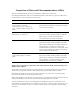
ASMi-52L Installation and Operation Manual Chapter 4 Configuration ASMi-52L System Status Device Type SHDSL Mode Clock Source Software Version Hardware Version FPGA Version Hardware Status PS MAC address IP address Alarm Indication Test Indication Local ASMi52_SA_L(PLASTIC) STU_C - 4W INT 1.00e06 0.00 0.01 NO HARDWARE FAILURE 48-60VDC/100-240VAC 00 20 d2 23 29 1b 172.17.161.73 MAJOR OFF Remote ASMi52_SA_L(PLASTIC STU_R - 4W RCV 1.00e06 0.00 0.
ASMi-52L Installation and Operation Manual Chapter 4 Configuration 4.5 Additional Tasks Accessing the Remote ASMi-52L Accessing the remote ASMi-52L is performed using a virtual connection with your terminal physically connected to the local unit. To access the remote ASMi-52L 1. From the Monitoring menu (Figure 4-27), select Open Virtual Connection 2. The Login screen of the second ASMi-52L appears. 3. Login to the second ASMi-52L You now have access to the second ASMi-52L menus.
ASMi-52L Installation and Operation Manual Chapter 4 Configuration ASMi-52L Change Access 1. User name ...() 2. Password ... 3. Clear User Name ... 4. Clear Password ... > ESC-prev.menu; !-main menu; &-exit; @-scroll 2. Select User Name to enter a new user name, select Password to enter a new password, select Clear User Name to delete the current user, or Clear User Name to delete the current password. 3. Enter a new user name or password and press . The Terminal menu appears. 4.
Chapter 4 Configuration ASMi-52L Installation and Operation Manual ASMi-52L Inventory 1 Index 1001 Description RAD-local ASMi-52_SA_L shdsl modem Vendor type Contained in 0 Class 3 Rel pos 0 Name shdsl modem HW ver 0.00 SW ver 1.00B1 ->> > ESC-prev.menu; !-main menu; &-exit; @-scroll; ?-help Figure 4-31.
ASMi-52L Installation and Operation Manual TFTP TFTP status TFTP error 1. TFTP IP server 2. TFTP file name 3. TFTP retry timeout 4. TFTP total timeout 5. Save 6. Transfer command > Chapter 4 Configuration ASMi-52L (No operation) (No error) (0.0.0.0) (asmi52.img) (15) (60) ESC - prev. menu ; ! – main menu ; & – exit Figure 4-32. TFTP Menu 2.
ASMi-52L Installation and Operation Manual Chapter 4 Configuration If you press , ASMi-52L aborts the download process and displays Download failure. Press Esc to continue. message in addition to the previous display. Note During the software installation, the TST indicator blinks. 2. Send the *.img file to ASMi-52L using the XMODEM protocol of your terminal application. Once the downloading is complete, ASMi-52L decompresses the release file, displaying the following message: Final process download.
ASMi-52L Installation and Operation Manual Chapter 4 Configuration Switching the Software Versions If an active software becomes corrupted, you can switch it with the backup in the local ASMi-52L units. To swap software versions: 1. Follow the path: File Utilities menu > File System > Swap SW files. The Swap SW Files menu appears. 2. From the Swap SW Files menu, select Swap Local SW Files to switch files in the local ASMi-52L.
ASMi-52L Installation and Operation Manual Chapter 4 Configuration Resetting ASMi-52L ASMi-52L supports four types of reset: • Reset to the default setting • SHDSL interface reset • SHDSL repeater line reset. • Overall reset Resetting to Default Settings You can reset the local or remote ASMi-52L to default settings. Resetting to the factory default does not affect the master clock setting.
ASMi-52L Installation and Operation Manual Chapter 4 Configuration Resetting the ASMi-52L Modem You can reset the SHDSL interface of the modem or repeater, or perform the overall reset of the modem. To reset the SHDSL interface or perform the overall device reset: 1. From the System Configuration menu, select Reset. The Reset menu appears (see Figure 4-35). 2. From the Reset menu, select Local Reset to reset the local modem, Remote Reset to reset remote device.
ASMi-52L Installation and Operation Manual Chapter 4 Configuration 3. From the Repeater Number menu, select repeater that you intend to reset. 4. From the Repeater Reset menu, select Repeater SHDSL Line Reset to reset the SHDSL line interface of the repeater. A confirmation message appears. 5. Type Y to confirm the reset. ASMi-52L Repeater Reset 1. Repeater SHDSL line reset... 2. Repeater number > (1) > ESC-prev.menu; !-main menu; &-exit; @-scroll Figure 4-37.
Chapter 5 Configuring a Typical Application 5.1 Overview This chapter provides detailed instructions for setting up two ASMi-52L modems in a typical application. Configuration of ASMi-52L is performed via menu-driven embedded software, using a standard ASCII terminal or a PC running a terminal emulation application connected to the rear panel CONTROL port. Alternatively, ASMi-52L can be managed from a Telnet host connected to the 10/100BASE-T port on the rear panel.
ASMi-52L Installation and Operation Manual Chapter 5 Configuring a Typical Application 5.2 Configuring the ASMi-52L units Two ASMi-52L units must be configured for this application. Both units have the same configuration parameters, except for the host IP address and the master clock mode. To prepare a control session: 1. Connect the terminal cable to the CONTROL connector of ASMi-52L. 2. Turn the control terminal on. 3. Configure the terminal to the default communication parameters: 9.
ASMi-52L Installation and Operation Manual Chapter 5 Configuring a Typical Application To set the device host IP address: 1. Display the host IP menu (Main menu > Configuration > System configuration > Management > Host IP. The host IP screen appears. 2. From the host IP menu, configure the following: CO ASMi-52L – 123.456.78.90 CPE ASMi-52L – 123.456.78.91 Host IP mask – 255.255.255.1 Host default gateway IP address – 255.255.255.2 ASMi-52L Host IP Host IP address (123.456.78.90) Host IP mask (255.255.
Chapter 5 Configuring a Typical Application ASMi-52L Installation and Operation Manual The display is refreshed and a new value appears (4W). 3. Select Save to save the change 4. Reset ASMi-52L in order to activate the change.
Chapter 6 Troubleshooting and Diagnostics This chapter describes the ASMi-52L diagnostic functions, which include: • Status indications, alarms, power-up self-test • Statistics collection • Diagnostic tests (loopbacks and LEDs test). 6.1 Monitoring Performance ASMi-52L has capabilities for collection of the SHDSL performance statistics. The statistics data is collected for the current 15-minute interval or current day.
ASMi-52L Installation and Operation Manual Chapter 6 Troubleshooting and Diagnostics ASMi-52L SHDSL port performances 1. SHDSL current performances ... 2. SHDSL all intervals local performances ... 3. SHDSL all intervals remote performances ... 4. SHDSL current day performances ... 5. SHDSL all days local performances ... 6. SHDSL all days remote performances ... 7. SHDSL clear local performances ... 8. SHDSL clear remote performances ... > ESC-prev.menu; !-main menu; &-exit; @-scroll Figure 6-2.
ASMi-52L Installation and Operation Manual Chapter 6 Troubleshooting and Diagnostics ASMi-52L SHDSL current day performance Local 24 hour ES (0) 24 hour UAS (0) 24 hour SES (0) 24 hour LOWS (0) 24 hour CRC (0) Cur. Day Timer (10 hour) Day Intervals (10) Remote (0) (0) (0) (0) (0) (10 hour) (10) ESC-prev.menu; !-main menu; &-exit; @-scroll Figure 6-4. SHDSL current day Performance Screen Table 6-1.
ASMi-52L Installation and Operation Manual Chapter 6 Troubleshooting and Diagnostics ASMi-52L SHDSL all intervals local/remote performances ... INTERVAL 1 CRC 0 LOSWS 0 ES 0 SES 0 UAS 0 ESC-prev.menu; !-main menu; &-exit; ?-help; @-scroll Figure 6-5. SHDSL all Intervals Performances ASMi-52L SHDSL all days local/remote performances ... DAY 1 CRC 0 LOSWS 0 ES 0 SES 0 UAS 0 ESC-prev.menu; !-main menu; &-exit; ?-help; @-scroll Figure 6-6.
ASMi-52L Installation and Operation Manual 6.3 Chapter 6 Troubleshooting and Diagnostics Handling Alarms ASMi-52L detects fault conditions and initiates alarms to alert the user. ASMi-52L supports the following alarm types: • System alarms, relating to the ASMi-52L chassis • Port alarms, relating to a specific interface (SHDSL or DTE) • Information messages (warnings) • Events that trigger alarm activation. ASMi-52L maintains two separate displays for the system and port alarms.
ASMi-52L Installation and Operation Manual Chapter 6 Troubleshooting and Diagnostics To clear the system log file: 1. From the System Monitoring menu (Figure 6-8), select System Clear Log File to clear the log file. A confirmation message is displayed at the bottom of the screen. 2. Type Y and press . All the system log file entries are deleted from the log file. ASMi-52L System System System System Monitoring status > log file clear log file ... > ESC-prev.
ASMi-52L Installation and Operation Manual Chapter 6 Troubleshooting and Diagnostics The Port Log File screen appears (see Figure 6-10). ASMI 52 Port log file Source Name 1 Local MNGMNT IS DOWN 2 Local SYNC LOSS LINE A severity MAJOR MAJOR Status time ON : 0:0:0 ON : 0:0:1 ESC-prev.menu; !-main menu; &-exit; @-scroll; ?-help 1 user(s) Figure 6-10. Port Log File Screen To clear the log file: 1. From the Physical Port Status menu, select Port Clear Log File to clear the log file.
ASMi-52L Installation and Operation Manual Chapter 6 Troubleshooting and Diagnostics Table 6-2. ASMi-52L Alarms and Warnings Number Terminal Message Port Description Severity 1 SELF TEST ERROR – Failure occurred during self-test Major 2 SOFTWARE DOWNLOAD – Software download is in progress Warning 3 LAN2 NOT CONNECTED DTE The Ethernet interface is not connected to LAN Major 4 LLB FROM DTE DTE Local loopback has been activated by physical connector (units with V.
ASMi-52L Installation and Operation Manual Chapter 6 Troubleshooting and Diagnostics Number Terminal Message Port Description Severity 23 NO DTE INTERFACE DTE No DTE interface is detected Major 42 WIRE MODE NOT COMP SHDSL Mismatch between line interface types (2/4-wire) between local and remote units Major 43 SPAN IS NOT FULL SHDSL Distance between adjacent repeaters is too long. You can identify the problematic segment by checking the Port Status screen.
ASMi-52L Installation and Operation Manual Chapter 6 Troubleshooting and Diagnostics Number Terminal Message Port Description Severity 56 LOSW FAILURE OVER NETWORK B SIDE SHDSL Loss of Sync Word is detected at the network side of the repeater Minor 57 LOSW FAILURE OVER CUSTOMER SIDE SHDSL Loss of Sync Word is detected at the customer side of the repeater Minor 58 LINE PARAMERS NOT COMP SHDSL Modems fail to synchronize due to the configuration parameters mismatch.
ASMi-52L Installation and Operation Manual 6.4 Chapter 6 Troubleshooting and Diagnostics Troubleshooting Use the chart shown in Table 6-4 to identify and remedy problems in unit operation. Table 6-4. Troubleshooting Chart Fault Probable Cause Remedial Action Power led off No power supplied to unit 1. Check power source. 2. Check power cable connected and correctly wired.
ASMi-52L Installation and Operation Manual Chapter 6 Troubleshooting and Diagnostics 6.5 Testing ASMi-52L The user-controlled test functions of ASMi-52L consists of the loopback tests and LEDs test. The purpose of these tests is to determine the source of a break in the data flow. Note • Loopbacks are supported in X.21 and V.35 versions only. • Both local and remote ASMi-52L units must be configured and synchronized properly to allow remote loopback activation.
ASMi-52L Installation and Operation Manual Chapter 6 Troubleshooting and Diagnostics The Diagnostics menu is displayed (see Figure 6-12). 2. From the Diagnostics menu, select: Local Test to run the LLB on the local ASMi-52L Remote Test to run the LLB on the remote ASMi-52L. The Local/Remote Test menu appears (see Figure 6-13). 3. Select LLB. The LLB value in parenthesis changes to ON. Also, an additional parameter, Loop Timeout, is displayed for the local ASMi-52L. 4.
ASMi-52L Installation and Operation Manual Chapter 6 Troubleshooting and Diagnostics Running the Remote Loopback The remote loopback (RLB) checks the performance of both the local and remote ASMi-52L modems, and the lines connecting them (see Figure 6-14). ASMi-52L allows you to set the loopback timeout causing the RLB to deactivate automatically after the desired period of time.
ASMi-52L Installation and Operation Manual Chapter 6 Troubleshooting and Diagnostics To activate the remote loopback at SHDSL repeater: 1. From the Diagnostics menu, select Repeater Test. The Repeater Test menu appears (see Figure 6-16). 2. From the Repeater Test menu, select Repeater Number and choose repeater at which you intend to activate the RLB Network. 3. From the Repeater Test menu, select RLB Network. The RLB Network value in parenthesis changes to ON.
Chapter 6 Troubleshooting and Diagnostics ASMi-52L Installation and Operation Manual Running the LEDs Test The user can perform the front-panel LED test to verify that the local unit indicators are functioning properly. To run the LEDs test: 1. From the Diagnostics menu (see Figure 6-12), select Local Test to run the LEDs test on the local ASMi-52L. The Local Test menu is displayed (see Figure 6-13). 2. Select LEDs Test. All the front-panel LED indicators light up for two seconds. 6.
Appendix A Interface Connector Specifications A.1 DTE Interface Connectors V.35 and X.21 Interface Connectors The V.35 interface of the ASMi-52 modem terminates in a 34-pin female connector. The X.21 interface terminates in a 15-pin, D-type female connector. Table A-1 lists the pin assignment of the V.35 and X.21 interface connectors. Table A-1. V.35 and X.21 Connector Pinouts Signal Function V.35 X.
ASMi-52 Installation and Operation Manual Appendix A Interface Connector Specifications Signal Function V.35 X.
ASMi-52L Installation and Operation Manual Appendix A Interface Connector Specifications A.2 CONTROL Connector The control terminal interface terminates in a V.24/RS-232 9-pin D-type female connector, which can be configured as DCE or DTE (see the Selecting the Control Port Interface section in Chapter 4). Table A-3 lists the CONTROL connector pin assignments. Table A-4 describes the control signal direction. Table A-3.
ASMi-52 Installation and Operation Manual Appendix A Interface Connector Specifications Table A-5.
Index —A— AC power connecting, 2-3 Aging timeout, 4-20 Alarms clearing, 6-6 displaying, 6-5 index of, 6-8 masking, 6-6 Autonegotiation, 4-20 —B— Baud Rate, 1-8 Bridge Table, 4-19 —C— Clock modes, 1-4, 4-6 ConfiguRAD, 1-4, 3-6 choosing options, 3-7 login, 3-7 navigating menus, 3-7 Connecting AC power, 2-3 DC power, 2-3 DTE interface, 2-2 line interface, 2-2 Connector control, A-3 DTE, A-1 Ethernet, A-2 specifications, A-1 Control port CTS state, 4-8 DSR state, 4-8 interface, 4-8 parameters, 4-7 —D
ASMi-52L Installation and Operation Manual Index —M— Management, 1-4 choosing options, 3-6 ConfiguRAD, 3-6 ConfiguRAD, 1-4 RADview, 1-4 saving changes, 3-6 access, 4-4 Manager list, 4-3 Menu configuration, 4-6 control port, 4-7 device information, 4-2 factory default, 4-30 host IP, 4-3 inventory, 4-26 LAN Configuration, 4-18 main, 4-5 management, 4-1 management access, 4-4 manager list, 4-3 master clock, 4-7 monitoring, 4-22 physical port status, 4-23 SHDSL Repeater Configuration, 4-16 software files,
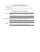
Supplement Drilling Template for Wall Installation Front Panel 1 1 176 mm (6.92 in) 3 3 2 2 101.6 mm (4 in) This panel is drawn to scale. To drill the holes for a wall installation, tear this page out of the manual or print it on letter-size paper (8.5"x11.0") and hold it against the wall. LEDs facing up - drill at 1. LEDs facing down - drill at 2. LEDs facing left - drill at 3.
24 Raoul Wallenberg St., Tel Aviv 69719, Israel Tel: +972-3-6458181, Fax: +972-3-6483331, +972-3-6498250 E-mail: erika_y@rad.com, Web site: www.rad.com Customer Response Form RAD Data Communications would like your help in improving its product documentation. Please complete and return this form by mail or by fax or send us an e-mail with your comments.
Error Report Type of Error(s) ❒ Incompatibility with product or Problem(s): ❒ Difficulty in understanding text ❒ Regulatory information (Safety, Compliance, Warnings, etc.) ❒ Difficulty in finding needed information ❒ Missing information ❒ Illogical flow of information ❒ Style (spelling, grammar, references, etc.) ❒ Appearance ❒ Other _________ Please list the exact page numbers with the error(s), detail the errors you found (information missing, unclear or inadequately explained, etc.
www.rad.com INTERNATIONAL HEADQUARTERS: 24 Raoul Wallenberg Street, Tel Aviv 69719, Israel, Tel: 972-3-6458181 Fax: 972-3-6498250, 972-3-6474436, Email: market@rad.com NORTH AMERICA HEADQUARTERS: 900 Corporate Drive, Mahwah, N.J. 07430, Tel: (201) 529-1100 Toll Free: 1-800-444-7234, Fax: (201) 529-5777, Email: market@radusa.com Publication No.