
Specifications


ASMi-52L Installation and Operation Manual Appendix A Interface Connector Specifications
CONTROL Connector A-3
A.2 CONTROL Connector
The control terminal interface terminates in a V.24/RS-232 9-pin D-type female
connector, which can be configured as DCE or DTE (see the Selecting the Control
Port Interface section in Chapter 4). Table A-3 lists the CONTROL connector pin
assignments. Table A-4 describes the control signal direction.
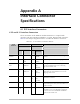
Table A-3. CONTROL Connector Pinout
Pin Function
1 Data Carrier Detect (DCD)
2 Receive Data (RD)
3 Transmit Data (TD)
4 Data Terminal Ready (DTR)
5 Ground (GND)
6 Data Set Ready (DSR)
7 Request To Send (RTS)
8 Clear To Send (CTS)
9 Ring Indicator (RI)
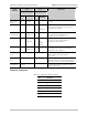
Table A-4. CONTROL Connector Signal Direction
Interface Type
Control Signal
DCE DTE
CTS Out Not Used
DCD Out Out
DSR Out Out
DTR In In
RI Not Used In
RTS In In
• When connected and turned on, the terminal sets the DTR line ON (active) to
gain control of the ASMi-52L and starts a configuration or monitoring session.
• In DTE mode, the DSR signal follows the RI signal
• In DCE mode, the DSR signal follows the DTR signal
When connecting a dial-out modem to the CONTROL port for the alarm
reporting, a cross cable must be used. Table A-5 pinout of a typical cross cable
with two male DB-9 connectors.
Note