Installation and Operation Manual ASMi-52 2/4-Wire SHDSL Modem
ASMi-52 2/4-Wire SHDSL Modem Installation and Operation Manual Notice This manual contains information that is proprietary to RAD Data Communications Ltd. ("RAD"). No part of this publication may be reproduced in any form whatsoever without prior written approval by RAD Data Communications.
Limited Warranty RAD warrants to DISTRIBUTOR that the hardware in the ASMi-52 to be delivered hereunder shall be free of defects in material and workmanship under normal use and service for a period of twelve (12) months following the date of shipment to DISTRIBUTOR.
General Safety Instructions The following instructions serve as a general guide for the safe installation and operation of telecommunications products. Additional instructions, if applicable, are included inside the manual. Safety Symbols Warning This symbol may appear on the equipment or in the text. It indicates potential safety hazards regarding product operation or maintenance to operator or service personnel.
Handling Energized Products General Safety Practices Do not touch or tamper with the power supply when the power cord is connected. Line voltages may be present inside certain products even when the power switch (if installed) is in the OFF position or a fuse is blown. For DC-powered products, although the voltages levels are usually not hazardous, energy hazards may still exist.
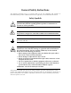
Connection of Data and Telecommunications Cables Data and telecommunication interfaces are classified according to their safety status. The following table lists the status of several standard interfaces. If the status of a given port differs from the standard one, a notice will be given in the manual. Ports Safety Status V.11, V.28, V.35, V.36, RS-530, X.
Caution Attention To reduce the risk of fire, use only No. 26 AWG or larger telecommunication line cords. Pour réduire les risques s’incendie, utiliser seulement des conducteurs de télécommunications 26 AWG ou de section supérieure. Some ports are suitable for connection to intra-building or non-exposed wiring or cabling only. In such cases, a notice will be given in the installation instructions. Do not attempt to tamper with any carrier-provided equipment or connection hardware.
Canadian Emission Requirements This Class A digital apparatus meets all the requirements of the Canadian Interference-Causing Equipment Regulation. Cet appareil numérique de la classe A respecte toutes les exigences du Règlement sur le matériel brouilleur du Canada. Warning per EN 55022 (CISPR-22) Warning This is a class A product. In a domestic environment, this product may cause radio interference, in which case the user will be required to take adequate measures.
Quick Start Guide Installation of ASMi-52 should be carried out only by an experienced technician. If you are familiar with ASMi-52, use this guide to prepare the units for operation. 1. Installing ASMi-52 Connecting the Interfaces 1. Connect the line to the RJ-45 rear panel connector dedicated SHDSL. 2. Connect the DTE to the appropriate rear panel connector. 3. Connect the control terminal to the rear panel CONTROL connector. Connecting the Power • Connect the AC or DC power to the ASMi-52 modem.
ASMi-52 Installation and Operation Manual Quick Start Guide Configuring the Master Clock To configure the master clock: • From the System Configuration menu (Main menu > Configuration > System Configuration > Master Clock), configure the central ASMi-52 clock to external or internal and remote ASMi-52 clock to the receive clock.
ASMi-52 Installation and Operation Manual Quick Start Guide To configure E1 parameters: • From the E1 Port Configuration menu (Main menu > Configuration > Port Configuration > E1 Port Configuration), configure the following E1 parameters: Framing mode Timeslot assignment. Note • You can configure timeslot 0 to be looped or transparent: Looped – timeslot 0 is sent back to the E1 interface, when operating opposite remote units with a serial data interface.
Quick Start Guide 4 Configuring ASMi-52 ASMi-52 Installation and Operation Manual
Contents Chapter 1. Introduction 1.1 Overview..................................................................................................................... 1-1 Versions................................................................................................................................ 1-1 Applications.......................................................................................................................... 1-2 Features.........................................................
Table of Contents Configuring the SHDSL Interface......................................................................................... 4-25 Configuring the Serial DTE Interface.................................................................................... 4-29 Configuring the E1 Interface................................................................................................ 4-31 Configuring the T1 Interface...................................................................................
Chapter 1 Introduction 1.1 Overview ASMi-52 is an SHDSL modem, which operates in full duplex over 2/4-wire lines and offers a cost-effective solution for delivering digital data to customer premises over the existing copper cables. ASMi-52 handles multiple data rates in the range of 64–4608 kbps. The modem supports X.21, V.35, RS-530, E1 and T1 interfaces. In addition, ASMi-52 may contain an Ethernet/Fast Ethernet bridge with VLAN support (via management LAN port) or an IP router (IR-IP).
ASMi-52 Installation and Operation Manual Chapter 1 Introduction Applications Figure 1-1 illustrates a typical ASMi-52 application, in which standalone modems operate opposite each other. Figure 1-2 shows a typical application of the remote ASMi-52 units with a centrally located ASMi-52CD dual modem cards. Central Office Customer Premises Fast Ethernet SNMP Management Station 2048 kbps E1 ASMi-52 ASMi-52 E1 10/100BT LAN PBX PBX 768 kbps ASMi-52 Public Network V.
ASMi-52 Installation and Operation Manual Chapter 1 Introduction Line Interface ASMi-52 extends the range of data transmission over 2/4-wire lines up to 7.0 km (4.3 miles), by employing SHDSL TC-PAM technology. ASMi-52 operation complies with the requirements of the ITU-T G.991.2 standard. 4-wire ASMi-52 units can be configured to operate over 4-wire or 2-wire lines. Table 1-1 lists typical ASMi-52 ranges over 2/4-wire 26 AWG line. Table 1-1.
ASMi-52 Installation and Operation Manual Chapter 1 Introduction ASMi-52 supports multiple data rates in the range between 64 kbps and 4608 kbps. Data rate depends on the following factors: • Unit rate mode (regular or low speed) • Line interface type (2-wire or 4-wire) • DTE interface type of the local and remote units (serial or E1) • Clock mode (internal or external).
ASMi-52 Installation and Operation Manual Chapter 1 Introduction Timing ASMi-52 supports three clock modes: • Internal, derived from its internal oscillator (CO mode) • External, supplied by the attached DTE • Receive, recovered from the received line signal (CPE mode). Management ASMi-52 supports the following management options: • SLIP via V.
ASMi-52 Installation and Operation Manual Chapter 1 Introduction Diagnostics ASMi-52 supports activation of the following: • Local loopback • Remote loopback • Remote loopback at SHDSL repeater (activated from the local unit). All tests can be activated from the local unit or from the remote unit. Real time alarms provide information on the system status, indicating management failure, synchronization loss and other conditions.
ASMi-52 Installation and Operation Manual Chapter 1 Introduction 1.3 Functional Description This section provides a functional description of ASMi-52 in the form of block diagrams (Figure 1-4 and Figure 1-5). Internal Oscillator Data & Clock DTE Interface Control Signals Modem Glue Logic SHDSL Line Interface CPU Data Bus Power Supply CPU 10/100BaseT Management Port LEDs and Terminal Interface Figure 1-4. ASMi-52/4W with V.
ASMi-52 Installation and Operation Manual Chapter 1 Introduction The ASMi-52 modem consists of the following major modules: DTE interface – Prepares the digital data coming from the DTE into a data stream for the modem glue logic. In addition it translates the data from the modem glue logic into digital data to be sent to the DTE. Internal oscillator – Serves as a source of internal clock for the ASMi-52 unit. Modem glue logic module – Processes the data from/to the SHDSL interface module.
ASMi-52 Installation and Operation Manual Control Port Ethernet Control Port Chapter 1 Introduction Type DTE/DCE Format 8 bits, no parity Baud Rate 9.6, 19.2, 38.4, 57.6, 115.2 kbps Connector 9-pin, D-type female Interface 10/100BaseT Protocol MAC Connector RJ-45 Derived from three alternative sources: Timing • Internal oscillator • External, from the attached DTE • Receive, derived from the received signal Diagnostics Loopbacks ITU V.
ASMi-52 Installation and Operation Manual Chapter 1 Introduction Physical Plastic Enclosure Height 43.7 mm / 1.7 in Width 240 mm / 9.4 in Depth 170.5 mm / 6.7 in Weight 0.5 kg / 1.1 lb Metal Enclosure Height 47.3 mm / 1.8 in Width 215 mm / 8.4 in Depth 147 mm / 5.8 in Weight 0.7 kg Power Source AC/DC Voltage Power Consumption / 1.
Chapter 2 Installation and Setup This chapter describes installation and setup procedures for the standalone ASMi-52 modem. After installing the unit: • Refer to Chapter 3 for the operating instructions. • Refer to Chapter 4 for the detailed system configuration procedures using an ASCII terminal connected to the ASMi-52 control port. If a problem is encountered, refer to Chapter 5 for test and diagnostic instructions.
Chapter 2 Installation and Setup ASMi-52 Installation and Operation Manual 2.
ASMi-52 Installation and Operation Manual Chapter 2 Installation and Setup Connecting the Interfaces Figure 2-1 illustrates the rear panel of ASMi-52 in a plastic enclosure with a 4-wire line interface, E1 DTE interface, user LAN interface, alarm relay port and the control port. Figure 2-2 illustrates the rear panel of ASMi-52 in a metal enclosure with a 4-wire line interface, the user LAN interface, and the control port. ALARM LINK TX 12 RX 45 LINE LINE B A 1 2 4 5 DCE SHDSL V.
Chapter 2 Installation and Setup ASMi-52 Installation and Operation Manual To connect the DTE: • Connect the DTE to the appropriate rear panel DTE interface connector of the ASMi-52 modem. Appendix A specifies the DTE connector pinouts. Connecting the Alarm Relay Connector To connect the alarm relay: • Connect external alarm device to the rear panel terminal block connector designated ALARM. Refer to Appendix A for the connector pinout and alarm functions.
Chapter 3 Operation This chapter provides the following information for the ASMi-52 modem: • ASMi-52 front-panel indicators • Operating procedures (turn-on, front-panel indications, performance monitoring and turn-off). • ASMi-52 default settings. Installation procedures given in Chapter 2 must be completed and checked before attempting to operate ASMi-52. 3.1 Indicators The front and rear panels of ASMi-52 include a series of LED indicators that show the current operating status of the unit.
ASMi-52 Installation and Operation Manual Chapter 3 Operation Table 3-1.
ASMi-52 Installation and Operation Manual Chapter 3 Operation Normal Indications Upon turning on ASMi-52, the PWR LED in the front panel lights to indicate that ASMi-52 is on. Table 3-3 shows the correct status of the indicators a few seconds after the units were synchronized. Table 3-3.
ASMi-52 Installation and Operation Manual Chapter 3 Operation Table 3-4. Default Settings (Cont.) 3-4 Parameter Default Value Telnet allowed Access allowed WEB allowed Access allowed Bootp state OFF DTS IP address 0.0.0.0 DTS IP mask 0.0.0.
ASMi-52 Installation and Operation Manual Chapter 3 Operation Table 3-4. Default Settings (Cont.) Parameter Default Value SHDSL Interface Transmission mode Annex B Power backoff Enable Snext margin Disable Current margin Disable Asym PSD Symmetrical Line prob Fixed rate Note: ASMi-52 units with 4-wire line interface support only fixed rate. Configured wire 4w Loop attenuation threshold 0 SNR margin threshold 0 Serial DTE Interface Rate ASMi-52, 2-wire and V.
Chapter 3 Operation 3-6 Default Settings ASMi-52 Installation and Operation Manual
Chapter 4 Managing ASMi-52 via a Terminal The configuration of ASMi-52 is performed via menu-driven embedded software, using a standard ASCII terminal or a PC running a terminal emulation application connected to the rear panel CONTROL port. Alternatively, ASMi-52 can be managed from a Telnet host connected to the 10/100BASE-T port on the rear panel. 4.1 Preparing for a Control Session This section describes how to prepare ASMi-52 and the supervisory terminal for a control session.
Chapter 4 Managing ASMi-52 via a Terminal ASMi-52 Installation and Operation Manual Preparing the Terminal Any standard ASCII terminal (a “dumb” terminal or a personal computer running a terminal emulation application) equipped with a V.24 (RS-232) communication interface can be used to configure ASMi-52. Appendix A details the pin assignment and control signal directions of the ASMi-52 control connector.
ASMi-52 Installation and Operation Manual Chapter 4 Managing ASMi-52 via a Terminal Figure 4-1. ConfiguRAD Login Managing ASMi-52 via Dedicated Timeslot ASMi-52 modems with E1 or T1 interface can be managed via dedicated E1/T1 timeslot (DTS) (see Figure 4-2). The DTS is a management channel that connects directly to ASMi-52 host using a separate IP interface, i.e. separate IP address and IP mask.
Chapter 4 Managing ASMi-52 via a Terminal ASMi-52 Installation and Operation Manual 4.2 Navigating the Management Menus This section provides a general description of the software menu operation and conventions for navigating the menus. Appendix C shows a map of the management menus in the ASMi-52 embedded software. Choosing Options To choose an option (terminal session): • Type the number corresponding to the option, and press . The screen for the selected option is displayed.
ASMi-52 Installation and Operation Manual Chapter 4 Managing ASMi-52 via a Terminal Navigating the ConfiguRAD Menus ConfiguRAD is a Web-based remote access terminal management software. It provides a user-friendly interface for configuring, collecting statistics and performing diagnostic tests on the ASMi-52 units. To choose an option: 1. Click a link in the ConfiguRAD screen to display the next menu. 2. Once the target screen is displayed, select a value from the drop-down box or enter it in a text box.
ASMi-52 Installation and Operation Manual Chapter 4 Managing ASMi-52 via a Terminal ASMi-52 USER NAME: PASSWORD: Figure 4-3. Password Request Screen (Terminal Session) Figure 4-4. Password Request Screen (ConfiguRAD Session) To enter the user name and password: 1. Type in your user name and press . Note You can leave the user name field empty (default), the default password is 1234. 2. Type in your password at the > prompt (up to eight characters). ASMi-52 responds to your entry with asterisks.
ASMi-52 Installation and Operation Manual Chapter 4 Managing ASMi-52 via a Terminal ASMi-52 Main menu ConfiguRAD utilities Figure 4-6. Main Menu (ConfiguRAD Session) 4.4 Displaying the ASMi-52 Inventory The ASMi-52 inventory displays information on the functional blocks of the local or remote modem. ASMi-52 consists of the following components: • SHDSL unit • DTE unit • Terminal control port • 10/100BASE-T port • Alarm relay port • Power supply. To display the ASMi-52 inventory: 1.
ASMi-52 Installation and Operation Manual Chapter 4 Managing ASMi-52 via a Terminal ASMi-52 Inventory 1 Index 1001 Description RAD-local ASMi-52_M shdsl modem Vendor type Contained in 0 Class 3 Rel pos 0 Name shdsl modem HW ver 0.00 SW ver 1.00E54 ->> > ESC-prev.menu; !-main menu; &-exit; @-scroll; ?-help Figure 4-7. Inventory Screen 4.5 Configuring ASMi-52 System Parameters This section describes the procedures for configuring system parameters of ASMi-52.
ASMi-52 Installation and Operation Manual Chapter 4 Managing ASMi-52 via a Terminal To display the System Configuration menu: • From the Configuration menu, select System Configuration. The System Configuration menu appears (see Figure 4-9). ASMi-52 System Configuration > 1. Master clock >(Internal) 2. Low Speed Operation (No) 3. Management > 4. LAN Configuration > 5. Control port > 6. Factory default > 7. Reset > 8. Save > ESC-prev.menu; !-main menu; &-exit; @-scroll Figure 4-9.
ASMi-52 Installation and Operation Manual Chapter 4 Managing ASMi-52 via a Terminal Configuring Low Speed Operation ASMi-52 can be configured to work at 64/128 kbps (2-wire) and 64/128/192/256 kbps (4-wire) when operating opposite devices with E1 DTE interface. The maximum data rate of ASMi-52 working in the low speed mode is 2048 kbps. To enable the low speed operation: 1. From the System Configuration, select Low Speed Operation. The option value changes to Yes or No. 2.
ASMi-52 Installation and Operation Manual Chapter 4 Managing ASMi-52 via a Terminal 2. From the Device Info menu, select Sys Contact and enter name of a contact person; select Sys Location and enter description of the ASMi-52 location; select Sys Name and enter a name of the unit. Note Information entered into the Sys Name field appears at the top of the configuration screens after the product name. 3. Press to return to the Management menu (see Figure 4-11). 4.
ASMi-52 Installation and Operation Manual Chapter 4 Managing ASMi-52 via a Terminal 4. Press to return to the Management menu (see Figure 4-11). 5. From the Management menu, select Save to save your changes. ASMi-52 Host IP 1. Host IP address (0.0.0.0) 2. Host IP mask (255.255.255.0) 3. Host default gateway (0.0.0.0) 4. Read community (public) 5. Write community (public) 6. Trap community (public) > ESC-prev.menu; !-main menu; &-exit; @-scroll Figure 4-13.
ASMi-52 Installation and Operation Manual Chapter 4 Managing ASMi-52 via a Terminal ASMi-52 Manager List 1. MNG 1 IP ... (0.0.0.0) 12. MNG 2 MASK ... (0.0.0.0) 2. MNG 2 IP ... (0.0.0.0) 13. MNG 3 MASK ... (0.0.0.0) 3. MNG 3 IP ... (0.0.0.0) 14. MNG 4 MASK ... (0.0.0.0) 4. MNG 4 IP ... (0.0.0.0) 15. MNG 5 MASK ... (0.0.0.0) 5. MNG 5 IP ... (0.0.0.0) 16. MNG 6 MASK ... (0.0.0.0) 6. MNG 6 IP ... (0.0.0.0) 17. MNG 7 MASK ... (0.0.0.0) 7. MNG 7 IP ... (0.0.0.0) 18.
ASMi-52 Installation and Operation Manual Chapter 4 Managing ASMi-52 via a Terminal ASMi-52 Management Access 1. SNMP allowed (access allowed) 2. TELNET allowed (access allowed) 3. WEB allowed (access allowed) > ESC-prev.menu; !-main menu; &-exit; @-scroll Figure 4-15. Management Access Menu Configuring Dedicated Timeslots ASMi-52 units with E1 or T1 port support management via a dedicated timeslot.
ASMi-52 Installation and Operation Manual Chapter 4 Managing ASMi-52 via a Terminal ASMi-52 Rem Agent Table SOURCE IP DESTINATION IP PORT 172.17.161.30 255.255.255.255 DTS 172.17.161.34 224.0.0.9 DSL 172.17.161.182 224.0.0.9 DSL 172.17.160.104 172.17.161.186 DTS > ESC-prev.menu; !-main menu; &-exit; @-scroll; ?-help Figure 4-17. Rem Agent Table Configuring the LAN Port ASMi-52 includes a 10/100BaseT port that can be used as a user or management port.
ASMi-52 Installation and Operation Manual Chapter 4 Managing ASMi-52 via a Terminal ASMi-52 LAN Configuration Operation Mode (Bridge) Bridging Mode (Switching) 1. Bridge Table []> 2. Aging Timeout(sec)[10 - 1000000] (10) 3. Auto negotiation (Enable) 4. Max AutoNeg Capability (100BASE_T-full duplex mode) 5. Fault indication (Yes) 6. LAN rate (2304) 7. Save > ESC-prev.menu; !-main menu; &-exit; @-scroll Figure 4-18.
ASMi-52 Installation and Operation Manual Chapter 4 Managing ASMi-52 via a Terminal 6. Select Save All to save the changes. 7. Press to exit the editing mode. To remove MAC address from the table: 1. From the Bridge Table, select MAC address that you intend to remove from the static table. 2. Enter editing mode, as explained above. 3. Enter all zeros for the MAC address value and save the change. ASMi-52 Bridge Table 1. Type (Static) MAC Address ... (00000000000) 2. Port ... () > ESC-prev.
ASMi-52 Installation and Operation Manual Chapter 4 Managing ASMi-52 via a Terminal ASMi-52 Data Rate (2304 Kbps) 1. 64 Kbps 12. 768 Kbps 23. 1472 Kbps 2. 128 Kbps 13. 832 Kbps 24. 1536 Kbps 3. 192 Kbps 14. 896 Kbps 25. 1600 Kbps 4. 256 Kbps 15. 960 Kbps 26. 1664 Kbps 5. 320 Kbps 16. 1024 Kbps 27. 1728 Kbps 6. 384 Kbps 17. 1088 Kbps 28. 1792 Kbps 7. 448 Kbps 18. 1152 Kbps 29. 1856 Kbps 8. 512 Kbps 19. 1216 Kbps 30. 1920 Kbps 9. 576 Kbps 20. 1280 Kbps 31.
ASMi-52 Installation and Operation Manual Chapter 4 Managing ASMi-52 via a Terminal 10BaseT full duplex 100BaseT half duplex 100BaseT full duplex. 6. From the LAN Configuration menu, select Save. Configuring Fault Indication If ASMi-52 fault indication is enabled and a fault condition or loss of signal is detected on the line, the Ethernet link is disconnected by ASMi-52. If fault indication is not selected, fault conditions are not passed through to the LAN side. To set the fault indication: 1.
ASMi-52 Installation and Operation Manual Chapter 4 Managing ASMi-52 via a Terminal 3. Select Save to save the changes. ASMi-52 Rate (9600 kbps) 1. 9600 kbps 2. 19200 kbps 3. 38400 kbps 4. 57600 kbps 5. 115200 kbps > ESC-prev.menu; !-main menu; &-exit; @-scroll Figure 4-23. Control Port Rate Menu Selecting the Control Port Interface To select the control port interface: 1.
ASMi-52 Installation and Operation Manual Chapter 4 Managing ASMi-52 via a Terminal To access the Port Control menu: • Path: Main Menu > Configuration > Control Port > Port Control. The Port Control menu appears (see Figure 4-24). ASMi-52 Port Control 1. Port Control Mode > (Terminal) 2. Terminal > 3. Dial out > 4. Save > ESC-prev.menu; !-main menu; &-exit; @-scroll Figure 4-24.
ASMi-52 Installation and Operation Manual Chapter 4 Managing ASMi-52 via a Terminal To access Terminal menu: • From the Port Control menu, select Terminal. The Terminal menu appears (see Figure 4-26). ASMi-52 Terminal 1. Change access > 2. POP ALARM (OFF) 3. Security timeout (10 min) 4. Save > ESC-prev.menu; !-main menu; &-exit; @-scroll Figure 4-26. Terminal Menu To change the user name and password: 1. From the Terminal menu, select Change Access.
ASMi-52 Installation and Operation Manual Chapter 4 Managing ASMi-52 via a Terminal To configure the security timeout: 1. From the Terminal menu, select Security Timeout to configure the timeout: FOREVER (timeout is disabled) or 10 MIN (idle disconnect time – 10 min). The display is refreshed and a new value appears. 2. Select Save to save the changes. To change the dial-out parameters: When the CONTROL port is configured to the dial out mode, you must specify the dial-out parameters of the port.
Chapter 4 Managing ASMi-52 via a Terminal ASMi-52 Installation and Operation Manual 4 to select the dialing mode. TONE, the dial-out modem is instructed to use DTMF dialing. PULSE, the dial-out modem is instructed to use pulse dialing. 5 to control the use of an alternate number. The alternate number is dialed after the specified number of call attempts on the primary number failed. ENABLE, the use of an alternate number is enabled.
ASMi-52 Installation and Operation Manual Chapter 4 Managing ASMi-52 via a Terminal Configuring the SHDSL Interface The ASMi-52 configuration software allows you to change the modem’s transmission mode (Annex A or Annex B). Examples given below illustrate the local device configuration procedures. To change the transmission mode: 1. Display the SHDSL Device Configuration menu (Configuration > Physical Ports Configuration > SHDSL Configuration menu > SHDSL Device Configuration).
ASMi-52 Installation and Operation Manual Chapter 4 Managing ASMi-52 via a Terminal ASMi-52 SHDSL local port configuration 1. Power backoff (Enable) 2. Snext margin (Disable) 3. Current margin (Disable) 4. Asym PSD (Symmetrical) 5. Line prob (Adaptive rate) 6. Configured wire (2W) 7. Loop attenuation threshold (dB) [0-127] (0) 8. SNR margin threshold (dB) [0-15] (0) 9. Save > ESC-prev.menu; !-main menu; &-exit; @-scroll Figure 4-29.
ASMi-52 Installation and Operation Manual Chapter 4 Managing ASMi-52 via a Terminal ASMi-52 Snext margin (Disable Snext margin) 1. -10 12. 1 2. -9 13. 2 3. -8 14. 3 4. -7 15. 4 5. -6 16. 5 6. -5 17. 6 7. -4 18. 7 8. -3 19. 8 9. -2 20. 9 10. -1 21. 10 11. 0 22. Disable Snext margin > ESC-prev.menu; !-main menu; &-exit; @-scroll Figure 4-30.
Chapter 4 Managing ASMi-52 via a Terminal ASMi-52 Installation and Operation Manual To configure the power spectral density: 1. From the SHDSL Port Configuration menu, select Asym PSD to choose the power spectral density value: symmetrical or asymmetrical. The display is refreshed and a new value appears. 2. Select Save to save the changes. Note Remote ASMi-52 units automatically detect the line power density. This parameter is permanently set to Sym/Asym Enable and cannot be changed.
ASMi-52 Installation and Operation Manual Chapter 4 Managing ASMi-52 via a Terminal Setting the SNR Margin Threshold You can set signal-to-noise ratio threshold. ASMi-52 generates minor alarm (SNR MARGIN OVER LINE A/B), if the signal-to-noise ratio on the line exceeds the threshold value. To set the SNR margin threshold: 1. From the SHDSL Port Configuration menu, select SNR margin threshold. 2. Enter the desired value (0 dB to 15 dB). 3. Select Save to save the changes.
ASMi-52 Installation and Operation Manual Chapter 4 Managing ASMi-52 via a Terminal Configuring LLB/RLB Activation from the DTE To enable/disable the LLB/RLB activation from the DTE: 1. From the Physical Ports Configuration menu, select DTE Configuration. The DTE Configuration menu appears (see Figure 4-32). 2. Select DTE local port configuration to configure the local DTE port or select DTE remote port configuration for the remote port configuration.
ASMi-52 Installation and Operation Manual Chapter 4 Managing ASMi-52 via a Terminal 2. Select the data rate by typing the number corresponding to the desired value, and press . The DTE Port Configuration menu appears. 3. Select Save to save the changes. ASMi-52 Data Rate (384 Kbps) 1. 64 Kbps 13. 2. 128 Kbps 14. 3. 192 Kbps 15. 4. 256 Kbps 16. 5. 320 Kbps 17. 6. 384 Kbps 18. 7. 448 Kbps 19. 8. 512 Kbps 20. 9. 576 Kbps 21. 10. 640 Kbps 22. 11. 704 Kbps 23. 12. 768 Kbps 24.
ASMi-52 Installation and Operation Manual Chapter 4 Managing ASMi-52 via a Terminal To access the E1 Port Configuration menu: 1. From the Physical Ports Configuration menu, select E1 Configuration. The E1 Configuration menu appears. 2. From the E1 Configuration menu, select E1 local port configuration for the local port configuration or select E1 remote port configuration for the remote port configuration. The E1 Port Configuration menu appears (see Figure 4-35). ASMi-52 E1 Local Port Configuration 1.
ASMi-52 Installation and Operation Manual Chapter 4 Managing ASMi-52 via a Terminal Selecting Resynchronization Time You can define time required for the E1 port operating in the framed mode to normal operation after loss of synchronization: • CCITT – As per requirements of ITU-T Rec.G.732 • Fast – After 1 sec • 62411 – As per requirements of AT&T TR-62411 (after 10 sec). To select resynchronization time: 1. From the E1 Port Configuration menu, select Sync Mode.
Chapter 4 Managing ASMi-52 via a Terminal ASMi-52 Installation and Operation Manual Mapping E1 Timeslots When working with framed E1, you can assign each timeslot to carry data or transmit idle code. To assign the MNG timeslot, DTS mode must be set to enable (see Figure 4-16). Only one timeslot can be assigned to MNG. To assign E1 timeslots: 1. From the E1 Port Configuration menu, select Time slots assign. The Timeslots Map menu appears (see Figure 4-38). 2.
ASMi-52 Installation and Operation Manual Time slot 1. TS0 2. TS1 3. TS2 4. TS3 5. TS4 6. TS5 7. TS6 8. TS7 9. TS8 10. TS9 11. TS10 12. TS11 13. TS12 14. TS13 15. TS14 16. TS15 map TRANS MNG DATA DATA DATA DATA DATA DATA DATA DATA DATA DATA DATA DATA DATA DATA Chapter 4 Managing ASMi-52 via a Terminal ASMi-52 17. 18. 19. 20. 21. 22. 23. 24. 25. 26. 27. 28. 29. 30. 31. 32.
Chapter 4 Managing ASMi-52 via a Terminal ASMi-52 Installation and Operation Manual Configuring the T1 Interface ASMi-52 units with T1 interface require configuration of the following parameters: • Framing mode: Unframed – Stream of bits at 1.
ASMi-52 Installation and Operation Manual Chapter 4 Managing ASMi-52 via a Terminal The T1 Port Configuration menu appears (see Figure 4-39). ASMi-52 T1 Local Port Configuration 1. Framed Mode 2. Line Code 3. Receive Gain 4. Interface 5. Fbit Configuration 6. Sync Mode 7. Idle code 8. Time slots assign 9. Units identical setting 10. Save >(UNFRAMED) (B8ZS) (LONG) > (Transparent) > (FAST (after 1 sec)) (ff) > (Yes) > ESC-prev.menu; !-main menu; &-exit; @-scroll Figure 4-39. T1 Port Configuration 4.
ASMi-52 Installation and Operation Manual Chapter 4 Managing ASMi-52 via a Terminal Displaying the System Status To display the system information: 1. Display the system status menu. (Path: Monitoring >System monitoring > System local/remote status) 2. Select System local status to display the local device status information or select System remote status to display the remote device status information. The System Status screen appears (see Figure 4-41).
ASMi-52 Installation and Operation Manual Chapter 4 Managing ASMi-52 via a Terminal ASMi-52 Port local status SHDSL (Standard ANNEX UNKNOWN, Wire mode 2W) SHDSL Line (Status: NOT SYNC, State: IDLE mode) Framer Type (SLOTTED T1) EOC compatible (STANDARD) Actual PSD (PSD UNKNOWN) Line rate (not applicable) T1 interface (IR-G704/BALANCE Data rate: 1536 kbps) HW status (NO HARDWARE FAILURE) Test status (NONE)> (N) ESC-prev.menu; !-main menu; &-exit; Figure 4-42.
ASMi-52 Installation and Operation Manual Chapter 4 Managing ASMi-52 via a Terminal 4.9 Updating Software Releases This section presents procedures for installing new software releases into the ASMi-52 units, as well as swapping existing software versions in a local or remote unit. ASMi-52 stores two software versions, each of them in one of the two 512-byte partitions of its flash memory, which also contains a boot program. The software is stored in compressed format.
ASMi-52 Installation and Operation Manual Chapter 4 Managing ASMi-52 via a Terminal Select TFTP Total Timeout and specify the TFTP connection timeout (in seconds). Select Save to save the TFTP configuration. Select Transfer Command to start downloading file to ASMi-52. ASMi-52 automatically erases the backup partition. Once the downloading is completed, ASMi-52 saves the new release as an active partition, the former active partition becomes backup.
Chapter 4 Managing ASMi-52 via a Terminal ASMi-52 Installation and Operation Manual To display the software version: 1. From the SW Files menu, (File Utilities menu > File System > SW files), select Local SW Files to display software revision of the local ASMi-52, or select Remote SW Files to display software revision of the remote device. The Local or Remote Software Version screen appears (see Figure 4-44). SW files Software active version: Software active partition: Code size: Date: 1.
ASMi-52 Installation and Operation Manual 4.10 Chapter 4 Managing ASMi-52 via a Terminal Resetting ASMi-52 ASMi-52 supports four types of reset: • Reset to the default setting • SHDSL interface reset • SHDSL repeater line reset. • Overall reset Resetting to Default Settings You can reset the local or remote ASMi-52 to default settings. Resetting to the factory default does not affect the master clock setting.
ASMi-52 Installation and Operation Manual Chapter 4 Managing ASMi-52 via a Terminal Resetting the ASMi-52 Modem You can reset the SHDSL interface of the modem or repeater, or perform the overall reset of the modem. To reset the SHDSL interface or perform the overall device reset: 1. From the System Configuration menu, select Reset. The Reset menu appears (see Figure 4-46). 2. From the Reset menu, select Local Reset to reset the local modem, Remote Reset to reset remote device.
ASMi-52 Installation and Operation Manual Chapter 4 Managing ASMi-52 via a Terminal 3. From the Repeater Number menu, select repeater that you intend to reset. 4. From the Repeater Reset menu, select Repeater SHDSL Line Reset to reset the SHDSL line interface of the repeater. A confirmation message appears. 5. Type Y to confirm the reset. ASMi-52 Repeater Reset 1. Repeater SHDSL line reset... 2. Repeater number > (1) > ESC-prev.menu; !-main menu; &-exit; @-scroll Figure 4-48. Repeater Reset Menu 4.
Chapter 4 Managing ASMi-52 via a Terminal 4-46 Exiting the Control Session ASMi-52 Installation and Operation Manual
Chapter 5 Configuring a Typical Application 5.1 Overview This chapter provides detailed instructions for setting up two ASMi-52 modems in a typical application. Configuration of ASMi-52 is performed via menu-driven embedded software, using a standard ASCII terminal or a PC running a terminal emulation application connected to the rear panel CONTROL port. Alternatively, ASMi-52 can be managed from a Telnet host connected to the 10/100BASE-T port on the rear panel.
ASMi-52 Installation and Operation Manual Chapter 5 Configuring a Typical Application 5.2 Configuring the ASMi-52 units Two ASMi-52 units must be configured for this application. Both units have the same configuration parameters, except for the host IP address and the master clock mode. To prepare a control session: 1. Connect the terminal cable to the CONTROL connector of ASMi-52. 2. Turn the control terminal on. 3. Configure the terminal to the default communication parameters: 9.
ASMi-52 Installation and Operation Manual Chapter 5 Configuring a Typical Application 3. Select Save to save the changes. To set the device host IP address: 4. Display the host IP menu (Main menu > Configuration > System configuration > Management > Host IP. The host IP screen appears. 5. From the host IP menu, configure the following: CO ASMi-52 – 123.456.78.90 CPE ASMi-52 – 123.456.78.91 Host IP mask – 255.255.255.1 Host default gateway IP address – 255.255.255.
ASMi-52 Installation and Operation Manual Chapter 5 Configuring a Typical Application ASMi-52 SHDSL local port configuration 1. Power backoff 2. Snext margin 3. Current margin 4. Asym PSD 5. Line prob 6. Configured wire 7. Loop attenuation threshold (dB) [0-127] 8. SNR margin threshold (dB) [0-15] 9. Save > ESC-prev.menu; !-main menu; &-exit; @-scroll (Enable) (Disable) (Disable) (Symmetrical) (Adaptive rate) (4W) (0) (0) 2. Select Configured wire The display is refreshed and a new value appears (4W).
Chapter 6 Troubleshooting and Diagnostics This chapter describes the ASMi-52 diagnostic functions, which include: • Status indications, alarms, power-up self-test • Statistics collection • Diagnostic tests (loopbacks and LEDs test). 6.1 Error Detection Power-Up Self-Test ASMi-52 performs a hardware self-test upon turn-on. The self-test sequence checks the critical circuit functions of the modem.
ASMi-52 Installation and Operation Manual Chapter 6 Troubleshooting and Diagnostics remains in the log file, enabling you to view the alarm history. Events enter only the log file. Displaying All Alarms ASMi-52 allows you to display all alarms, irrespective of their origin (system or port). To display all alarms: 1. From the Main menu, select Monitoring. The Monitoring menu appears (see Figure 6-1). 2. From the Monitoring menu, select Total Alarms. The Total Alarms Screen appears (see Figure 6-2).
ASMi-52 Installation and Operation Manual Chapter 6 Troubleshooting and Diagnostics Displaying System Alarms To display the system alarms: 1. From the Main menu, select Monitoring. 2. From the Monitoring menu, select System Monitoring. The SystemMonitoring menu appears (see Figure 6-3). 3. Select Device Local Alarms to display the local device alarms or type Device Remote Alarms to display the remote device alarms. The Device Alarms screen appears (see Figure 6-4).
ASMi-52 Installation and Operation Manual Chapter 6 Troubleshooting and Diagnostics 2. Type Y and press . All the system log file entries are deleted from the log file. Displaying Port Alarms 1. Follow the path: Main menu > Monitoring > Physical Port Monitoring > Physical Port Status The Physical Port Status menu appears. 2.
ASMi-52 Installation and Operation Manual Chapter 6 Troubleshooting and Diagnostics To display the log file: 1. From the Monitoring menu, select Physical Ports Monitoring. The Physical Ports Monitoring menu appears. 2. Select Physical Port Local Status to display the local port status or select Physical Port Remote Status to display the remote port status. The Physical Port Local/Remote Status menu appears (see Figure 6-5). 3. From the Physical Port Local/Remote Status menu, select Port Log File.
ASMi-52 Installation and Operation Manual Chapter 6 Troubleshooting and Diagnostics Table 6-1. ASMi-52 Alarms and Warnings Number Terminal Message Port Description Severity 1 SELF TEST ERROR – Failure occurred during self-test Major 2 SOFTWARE DOWNLOAD – Software download is in progress Warning 4 LLB FROM DTE DTE Local loopback has been activated by physical connector (units with V.
ASMi-52 Installation and Operation Manual Chapter 6 Troubleshooting and Diagnostics Table 6-1. ASMi-52 Alarms and Warnings (Cont.
ASMi-52 Installation and Operation Manual Chapter 6 Troubleshooting and Diagnostics Table 6-1. ASMi-52 Alarms and Warnings (Cont.) Number Terminal Message Port Description Severity 42 WIRE MODE NOT COMP SHDSL Mismatch between line interface types (2/4-wire) between local and remote units Major 43 SPAN IS NOT FULL SHDSL Distance between adjacent repeaters is too long. You can identify the problematic segment by checking the Port Status screen.
ASMi-52 Installation and Operation Manual Chapter 6 Troubleshooting and Diagnostics Table 6-2. ASMi-52 Events (Cont.) Terminal Message Description GS OUT OF SYNC ABORT SHDSL framer out of sync GS LOSS OF CARRIER DETECT SHDSL carrier loss GS SQ ERROR DETECT SHDSL signal quality value is more than 22.
ASMi-52 Installation and Operation Manual Chapter 6 Troubleshooting and Diagnostics ASMi-52 SHDSL statistics 1. SHDSL current performances ... 2. SHDSL all intervals performances ... 3. SHDSL current day performances ... 4. SHDSL all days performances ... 5. SHDSL clear performances > ESC-prev.menu; !-main menu; &-exit; @-scroll Figure 6-9. SHDSL Statistics Menu 3.
ASMi-52 Installation and Operation Manual Chapter 6 Troubleshooting and Diagnostics ASMi-52 SHDSL current day performance Port number (1) 24 hour ES (0) 24 hour UAS (0) 24 hour SES (0) 24 hour LOWS (0) 24 hour CRC (0) Cur. Day Timer (10 hour) Day Intervals (10) ESC-prev.menu; !-main menu; &-exit; @-scroll Figure 6-11. SHDSL current day Performance Screen Table 6-3.
ASMi-52 Installation and Operation Manual Chapter 6 Troubleshooting and Diagnostics ASMi-52 SHDSL all intervals performances ... INTERVAL 1 CRC 0 LOSWS 0 ES 0 SES 0 UAS 0 ESC-prev.menu; !-main menu; &-exit; ?-help; @-scroll Figure 6-12. SHDSL all Intervals Performances SHDSL all days performances ... DAY 1 CRC 0 ASMi-52 LOSWS 0 ES 0 SES 0 UAS 0 ESC-prev.menu; !-main menu; &-exit; ?-help; @-scroll Figure 6-13.
ASMi-52 Installation and Operation Manual Note Chapter 6 Troubleshooting and Diagnostics • For the details on enabling the CRC-4 function, refer to Enabling CRC-4 Code Generation in Chapter 4. • For the details on configuring T1 framing, refer to Configuring T1 Interface in Chapter 4. Displaying the Current E1/T1 Statistics To display the current E1 statistics: 1.
ASMi-52 Installation and Operation Manual Chapter 6 Troubleshooting and Diagnostics ASMi-52 E1 current day performance Current ES Current UAS Current SES Current BES Current LOFC Current CSS 24 hour degrade min 24 hour last degrade min 24 intervals (0) (0) (0) (1) (0) (0) (0) (0) (2) ESC-prev.menu; !-main menu; &-exit; @-scroll Figure 6-16.
ASMi-52 Installation and Operation Manual Chapter 6 Troubleshooting and Diagnostics Table 6-4. E1 Statistics Parameters (Cont.) Display Description Current UAS Range 15 min 24 hour Number of unavailable seconds in which a failed signal occurred during the current interval. This value is updated every second for 15-minute interval or every 15 min. for 24-hour interval. 0–900 0–65535 Current BES Number bursty errored seconds, in which 2 to 831 CRC error events occurred during the current interval.
ASMi-52 Installation and Operation Manual Chapter 6 Troubleshooting and Diagnostics E1 all intervals performances ... INTERVAL 1 ES 0 SES 0 ASMi-52 UAS 0 BES 0 LOFC 0 CSS 0 DM 0 ESC-prev.menu; !-main menu; &-exit; @-scroll; ?-help Figure 6-18. E1 All Intervals Performances Clearing the E1 Statistics To clear the E1 statistics: • From the E1 Statistics menu (see Figure 6-9), select E1 Clear Performances. All E1 statistics data is cleared. 6.
ASMi-52 Installation and Operation Manual Chapter 6 Troubleshooting and Diagnostics Local ASMi-52 Data Clock Transmit Local DTE Glue Logic Line Interface Data Clock Receive Figure 6-19. Local Loopback To run the local loopback: 1. From the Main menu, select Diagnostics. The Diagnostics menu is displayed (see Figure 6-20). 2. From the Diagnostics menu, select: Local Test to run the LLB on the local ASMi-52 Remote Test to run the LLB on the remote ASMi-52.
ASMi-52 Installation and Operation Manual Chapter 6 Troubleshooting and Diagnostics ASMi-52 Local Test or Remote Test LLB from DTE: OFF RLB from DTE: OFF 1. 2. 3. 4. 5. LLB (ON) Loop Timeout (min)(0-4095) LEDs test Clear all Save ...(5) > ESC-previous menu ; !–main menu ; &–exit; @-scroll Figure 6-21. Local/Remote Test Menu Running the Remote Loopback The remote loopback (RLB) checks the performance of both the local and remote ASMi-52 modems, and the lines connecting them (see Figure 6-22).
ASMi-52 Installation and Operation Manual Chapter 6 Troubleshooting and Diagnostics 2. Select RLB. The RLB value in parenthesis changes to ON. Also, an additional parameter, Loop Timeout, is displayed for the local ASMi-52. 3. Select Loop Timeout, if you want to set loopback timeout (in minutes). The Loop Timeout value changes. Note Loop timeout = 0 is forever! 4. Once you selected the loopback timeout, select Save to activate the RLB. The RLB is initiated.
ASMi-52 Installation and Operation Manual Chapter 6 Troubleshooting and Diagnostics ASMi-52 Repeater Test 1. RLB Network (ON) 2. Loop Timeout(min)[0 - 4095] 3. Repeater number 4. Save ... (5) > (1) > ESC-previous menu ; !–main menu ; &–exit Figure 6-24. Repeater Test Menu Deactivating the Loopbacks To deactivate a running loopback: • From the Local or Remote Test menu, type the number corresponding to the loopback in progress to change its value from ON to OFF and choose Save.
Appendix A Interface Connector Specifications A.1 DTE Interface Connectors V.35, X.21 and RS-530 Interface Connectors The V.35 interface of the ASMi-52 modem terminates in a 34-pin female connector. The X.21 interface terminates in a 15-pin, D-type female connector. The RS-530 interface terminates in 25-pin, D-type female connector. Table A-1 lists the pin assignment of the V.35, X.21 and RS-530 interface connectors. Table A-1. V.35, X.21 and RS-530 Connector Pinouts Signal Function Pin V.35 RS-530 X.
ASMi-52 Installation and Operation Manual Appendix A Interface Connector Specifications Table A-1. V.35, X.21 and RS-530 Connector Pinouts (Cont.) Signal Function V.35 RS-530 X.
ASMi-52 Installation and Operation Manual Appendix A Interface Connector Specifications E1 and T1 Interface Connector The balanced E1 and T1 interfaces terminate in RJ-45 connector. Table A-2 lists the balanced connector pin assignment. Table A-2. E1/T1 Connector Pinout Pin Function 1, 2 Transmit (output) 4, 5 Receive (input) 7 CPU ID for unbalanced interface detection 8 Earth GND Ethernet Connector Table A-3.
ASMi-52 Installation and Operation Manual Appendix A Interface Connector Specifications A.2 CONTROL Connector The control terminal interface terminates in a V.24/RS-232 9-pin D-type female connector which can be configured as DCE or DTE (see the Selecting the Control Port Interface section in Chapter 4). Table A-4 lists the CONTROL connector pin assignments. Table A-5 describes the control signal direction. Table A-4.
ASMi-52 Installation and Operation Manual Appendix A Interface Connector Specifications Table A-6. Cross Cable Pinout DB-9 Pin DB-9 Pin 2 3 3 2 4 6 5 5 6 4 7 8 8 7 A.3 Alarm Relay Connector The ASMi-52 alarm relay terminates in a 9-pin female connector, designated ALARM. Figure A-1 lists the pinout of the ALARM connector. Figure A-2 shows the pin functions. The relay positions are shown in the Alarm Active state. 6 5 4 3 2 1 Figure A-1.
Appendix A Interface Connector Specifications A-6 Alarm Relay Connector ASMi-52 Installation and Operation Manual
Appendix B IR-IP Interface Module Table of Contents B.1 INTRODUCTION ..............................................................................................................B-1 Overview.................................................................................................................B-1 Application ..............................................................................................................B-2 B.2 TECHNICAL SPECIFICATIONS .................................................
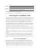
ASMi-52 Installation and Operation Manual Appendix B IR-IP Interface Module B.1 Introduction Overview IR-IP is a high-performance, miniature IP router based on RAD's unique IP router chip, the ChipRouter. IR-IP has a 10BaseT (UTP) interface and complies with IEEE 802.3. The router interface operates in either half-duplex or full-duplex mode. IR-IP filters the traffic, in accordance with the IP address of each packet, and forwards only packets with foreign addresses through the WAN link.
ASMi-52 Installation and Operation Manual Appendix B IR-IP Interface Module B.2 Technical Specifications Router LAN WAN Local IP Net Capacity Supports up to 256 hosts on the local LAN IP net Filtering Rate 35,000 packets per second IR-IP:technical specifications Forwarding Rate 30,000 packets per second Buffer 256 frames (maximum size – 1534 bytes) Delay 1 frame Configuration Telnet, through the 10BaseT interface Standard Conforms to IEEE 802.
ASMi-52 Installation and Operation Manual Appendix B IR-IP Interface Module B.3 Physical Description Figure B-2 shows the rear panels of ASMi-52 with the IR-IP interface module. TX 12 ALARM LINK RX 45 LINE LINE B A 1 2 4 5 1 2 3 4 ACT SETUP CONTROL E1/T1 LINK ERR SHDSL ACT IR-IP Figure B-2. IR-IP Ethernet Router Table B-1 provides the pinout of the 10BaseT RJ-45 connector. Table B-1.
ASMi-52 Installation and Operation Manual Appendix B IR-IP Interface Module IR-IP LEDs IR-IP contains three LEDs, which indicate the module activity. Table B-3 explains the functions of the IR-IP interface indicators. Table B-3.
Appendix B IR-IP Interface Module ASMi-52 Installation and Operation Manual B.
ASMi-52 Installation and Operation Manual Appendix B IR-IP Interface Module Default IP Communication Parameters The factory-default IP communication parameters of the interface module are: • The default IP address of the IR-IP Ethernet port is 192.168.205.1, and the default IP subnet mask is 255.255.255.252. • The port will accept IP communication only from the IP address 192.168.205.2.
Appendix B IR-IP Interface Module ASMi-52 Installation and Operation Manual Connecting the Telnet Host Before starting the management and configuration activities, it is necessary to establish IP communication between your Telnet host and the IR-IP interface module. For this purpose, it is necessary to provide a communication path. Because of the method used to assign an IP address to IR-IP Ethernet port, it is recommended to connect the Telnet host directly to the IP router 10BASE-T connector.
ASMi-52 Installation and Operation Manual Appendix B IR-IP Interface Module The IP address is actually retrieved from the ARP frames sent during pinging to locate the ping destination, not from the ping frames. To ensure that the process is correctly performed, it is recommended to check the contents of the ARP table before starting the ping utility, to make sure that it does not contain the address to be assigned to the IP router LAN interface.
Appendix B IR-IP Interface Module ASMi-52 Installation and Operation Manual Changing the LAN IP Address of a Configured IR-IP The LAN IP address of an already-configured IR-IP can be changed while it operates. This means it is not necessary to turn ASMi-52 off before starting the configuration procedure. Note however that the IP traffic flow through IR-IP will be disrupted until the other stations in the IP network learn the new address.
ASMi-52 Installation and Operation Manual Appendix B IR-IP Interface Module B.6 IR-IP Management Utility General Operating Procedures The IR-IP interface module is managed via a simple, menu-driven utility that uses a basic terminal user interface. A typical screen is shown in Figure B-3. As seen in Figure B-3, each screen has a header that identifies the device being configured and its logical name, assigned by the user, followed by the running software revision and date.
ASMi-52 Installation and Operation Manual Appendix B IR-IP Interface Module Menu Structure of Management Utility Figure B-4 shows the menu structure of the IR-IP management utility. Main Menu 1. Quick Setup 2. Management Access 3. Advanced Setup 1.Telenet Password 2. Telenet Activity Timeout 3. SNMP Access 4. SNMP Read Community 5. SNMP Write Community 6. SNMP Trap Community 7. SNMP Management Table 1. LAN IP Address 2. LAN IP Mask 3. WAN IP Address 4. WAN IP Mask 5. Default Gateway 6.
ASMi-52 Installation and Operation Manual Appendix B IR-IP Interface Module 2. Enter addresses for LAN IP, LAN IP Mask, WAN IP, WAN IP mask, default gateway and DHCP server. LAN IP Address – The LAN IP address for the IP router LAN interface, is the address to which nodes connected to the local LAN send packets that are addressed to the WAN. LAN IP Mask – Used to enter the IP subnet mask. The IP router supports a maximum of 254 hosts on the LAN, therefore you must use Class C subnet masks.
ASMi-52 Installation and Operation Manual Appendix B IR-IP Interface Module To use this option, enter the IP address of another router attached to the local LAN in the Default Gateway field. Note It is very important to obtain the correct parameters from the system administrator or ISP. The most common problem when establishing an IP connection is incorrect configuration of IP parameters and default gateway. Do not try to guess these parameters.
ASMi-52 Installation and Operation Manual Appendix B IR-IP Interface Module B.8 Defining Management Access The Management Access menu is used to enable the use of passwords to protect the access to IR-IP management utility, and control the inactivity time-out interval. When password protection is enabled, a Telnet management session can start only after the correct password is entered. To access the Management Access menu: • From the Main menu, type 2. The Management Access menu appears (Figure B-8).
ASMi-52 Installation and Operation Manual Appendix B IR-IP Interface Module B.9 Advanced Setup The Advanced Setup menu is used to select the desired group of IR-IP configuration parameters. The parameters accessed through Advanced Setup menu supplement the parameters available on the Quick Setup screen, by providing control over all the other IR-IP parameters. To perform advanced setup: • From the Main menu, press 3. The Advanced Setup menu appears (Figure B-9). IR_IP S/W Ver. 1.
ASMi-52 Installation and Operation Manual Appendix B IR-IP Interface Module IR_IP S/W Ver. 1.21 (date) Quick Setup Management Access Advanced Setup ................................................................. Device identification Interface Parameters ================================================================= 1. LAN Status :[ Open ] 2. WAN Status :[ Open ] 3. WAN Throttle :[ Full ] 4. Aging Timeout (min) :5. Press one of the numbers to select or ESC: Figure B-10.
ASMi-52 Installation and Operation Manual Appendix B IR-IP Interface Module Defining the WAN Protocol Parameters Frame Relay Protocol The Frame Relay Protocol Parameters menu is used to configure the parameters Frame Relay WAN for protocol (the WAN protocol is selected by means of the Quick Setup ) in Figure B-5. To define the Frame Relay protocol parameters: 1. From the Advanced Setup menu, type 3. (A typical Frame Relay Protocol Parameters menu is shown in Figure B-11.) 2.
ASMi-52 Installation and Operation Manual Appendix B IR-IP Interface Module PPP Protocol Menu The PPP Protocol Parameters menu is used to configure the parameters PPP WAN for protocol (the WAN protocol is selected by means of the (the WAN protocol is selected by means of the Quick Setup ) in Figure B-5. To define the PPP Protocol Parameters: 1. From the Advanced Setup menu, type 3. A typical PPP Protocol Parameters menu is shown in Figure B-12. 2.
ASMi-52 Installation and Operation Manual Appendix B IR-IP Interface Module Defining the Multicast Parameters The Multicast IP menu is used to specify the IP multicast frame forwarding parameters, and to access the static multicast groups’ table. To define the Multicast Parameters: 1. From the Advanced Setup menu, press 4. The Multicast IP menu appears (Figure B-13). IR_IP S/W Ver. 1.21 (date) Quick Setup Management Access Advanced Setup ............................................................
ASMi-52 Installation and Operation Manual IR_IP Appendix B IR-IP Interface Module Group IP Address 1. ................ 2. ................ 3. ................ 4. ................ 5. ................ 6. ................ 7. ................ 8. ................ 9. ................ 10. ............... S/W Ver. 1.21 (date) Static Multicast Groups Table ----------------------------- Press 'A'-add, 'E'-edit, 'D'-delete, 'C'-clear all, 'ESC'-exit: Figure B-14. Static Multicast Groups Table 2.
ASMi-52 Installation and Operation Manual Appendix B IR-IP Interface Module The New Software Download menu is used to specify the software downloading parameters. To download new software: 1. From the Device Control submenu, type 1. New Software Download menu appears (Figure B-16). IR_IP S/W Ver. 1.21 (date) Quick Setup Management Access Advanced Setup Device Control .....................................................................
ASMi-52 Installation and Operation Manual Appendix B IR-IP Interface Module Resetting IR-IP The Reset menu allows you to perform reset of IR-IP, or its interfaces. This operation can be used to restore normal operation after service is disrupted by an abnormal condition. Any data stored in the IR-IP buffers is discarded, and the flow of traffic is temporarily interrupted. IR_IP S/W Ver. 1.21 (date) Quick Setup Management Access Advanced Setup Device Control .....................................
ASMi-52 Installation and Operation Manual Appendix B IR-IP Interface Module Note Resetting the WAN interface causes the WAN controller to be restarted. This results in renegotiation of the WAN protocol parameters. To continue your Telnet session, press any key within 15 seconds following the confirmation of the reset operation. B.
ASMi-52 Installation and Operation Manual IR_IP Appendix B IR-IP Interface Module S/W Ver. 1.21 (date) BOOT Version Device Name System Location Contact Person VIEW CONFIGURATION -----------------:1.06 18.03.1999 :IP router card :The location of this device :Name of contact Person MAC Address Default Gateway : 00-20-D2-16-3F-9B : WAN Intrf Type Baud(Kbps) Prot IP Address IP Mask Status ..................................................................... LAN UTP ------Ethr 192.168.205.
ASMi-52 Installation and Operation Manual Appendix B IR-IP Interface Module IR_IP S/W Ver. 1.21 (date) Multicast Groups Table ---------------------Group IP Address Status Group IP Address Status Press any key for exit Figure B-21. Multicast Groups Table Screen Viewing the Statistics Screen The Statistics screen is used to display statistical information on the traffic between the networks connected by IR-IP. The data displayed on this screen enables you to evaluate the IR-IP performance.
ASMi-52 Installation and Operation Manual IR_IP WAN WAN WAN WAN WAN WAN WAN WAN WAN Appendix B IR-IP Interface Module Counter Name in Octets Out Octets Out Frames to LAN Frames Transfer IP Datagram Received to CPU Discarded to LAN Discarded Out Errors CRC Errors S/W Ver. 1.
ASMi-52 Installation and Operation Manual Appendix B IR-IP Interface Module Using the Ping Function The Ping option is used to confirm IP connectivity by pinging other IP hosts. Connectivity is confirmed by receiving a reply from the remote (pinged) IP host. To ping a host: 1. From the Diagnostic Tools menu, type 1 and enter the desired host IP address. 2. Press to confirm the destination IP address. 3. To start pinging, type 2 on the Diagnostic Tools screen.
ASMi-52 Installation and Operation Manual • Appendix B IR-IP Interface Module When you cannot configure IR-IP because its current LAN-interface IP address and/or the Telnet password, are not known. To erase the user’s configuration: 1. Turn ASMi-52 off. 2. Set all the four sections of the IR-IP DIP switch (see Table B-2) to ON. 3. Turn ASMi-52 on and monitor the ERR and LINK indicators: they must blink alternately. 4.
ASMi-52 Installation and Operation Manual Appendix B IR-IP Interface Module Note If you do not set sections 3 and 4 to OFF within 15 seconds of power-up, IR-IP ignores the setting of all the four sections to ON and starts normal operation. In this case, it is recommended to turn ASMi-52 off and then back on. Alternately, to abort the whole operation, turn ASMi-52 off, return all the four switches to the desired positions, and then turn ASMi-52 on again. 5.
ASMi-52 Installation and Operation Manual Appendix B IR-IP Interface Module Erasing IR-IP Software B-31
Appendix C Configuration Menus This appendix lists all menus of the ASMi-52 management software. Main menu 1. Inventory 2. Configuration 1. System Configuration 1. Master Clock 1. Receive 2. Internal 3. External 2. Management 1. Device info 1. Sys contact 2. Sys location 3. Sys name 4. Clear sys params 2. Host IP 1. Host IP address 2. Host IP mask 3. Host default gateway 4. Read community 5. Write community 6. Trap community 3. Manager list 4. Management access 1. SNMP allowed 2. Telnet allowed 3.
ASMi-52 Installation and Operation Manual Appendix C Configuration Menus Notes Some of the management menu options depend on the type of the DTE interface installed in ASMi-52: • DTS Configuration (Main menu > Configuration > Management) is available only for the units with E1 or T1 interface. • LAN Rate (Main menu > Configuration > LAN Configuration) is available for the units with the user 10/100BaseT port.
Index —A— Adapter cable, 1-3 Aging timeout, 4-17 Alarm Relay, 1-9 connecting, 2-4 Alarms clearing, 6-3 displaying, 6-2 index of, 6-6 masking, 6-4 ASMi-52 Menu map, C-1 Autonegotiation, 4-18 —B— Baud Rate, 1-9 Bridge Table, 4-16 —C— Clock modes, 1-5, 4-9 ConfiguRAD, 1-5 Connector DTE, A-1 E1/T1, A-3 Ethernet, A-3 Control port CTS state, 4-20 DSR state, 4-20 interface, 4-20 parameters, 4-19 —D— Data Rates, 1-4 Dedicated timeslot, 4-3, 4-14 configuration, 4-14 Default gateway, 4-11 Default settings, 3-3
ASMi-52a Installation and Operation Manual Index Reset WAN, B-23 static groups, B-20 statistics, B-26 technical specifications, B-3 —L— LAN Aging timeout, 4-17 autonegotiation, 4-18 Configuration, 4-15 fault indication, 4-19 operation mode, 4-15 rate, 4-17 LED test, 6-20 Line Interface, 1-3, 1-8 Log file, 6-3 Logging out, 4-5 Loopback, 1-9 activating, 6-16 clearing, 6-20 local, 1-9, 6-16 remote, 1-9, 6-18 repeater test, 6-19 Low speed mode, 4-10 —M— Management, 1-5, 4-2 ConfiguRAD, 1-5, 4-2 RADview, 1-
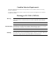
24 Raoul Wallenberg St., Tel Aviv 69719, Israel Tel: +972-3-6458181, Fax: +972-3-6483331, +972-3-6498250 E-mail: erika_y@rad.com, Web site: www.rad.com Customer Response Form RAD Data Communications would like your help in improving its product documentation. Please complete and return this form by mail or by fax or send us an e-mail with your comments.
Error Report Type of Error(s) ❒ Incompatibility with product or Problem(s): ❒ Difficulty in understanding text ❒ Regulatory information (Safety, Compliance, Warnings, etc.) ❒ Difficulty in finding needed information ❒ Missing information ❒ Illogical flow of information ❒ Style (spelling, grammar, references, etc.) ❒ Appearance ❒ Other _________ Please list the exact page numbers with the error(s), detail the errors you found (information missing, unclear or inadequately explained, etc.
www.rad.com INTERNATIONAL HEADQUARTERS: 24 Raoul Wallenberg Street, Tel Aviv 69719, Israel, Tel: 972-3-6458181 Fax: 972-3-6498250, 972-3-6474436, Email: market@rad.com U.S. HEADQUARTERS: 900 Corporate Drive, Mahwah, N.J. 07430, Tel: (201) 529-1100 Toll Free: 1-800-444-7234, Fax: (201) 529-5777, Email: market@radusa.com Publication No.