
Specifications


Appendix B IR-IP Interface Module ASMi-52 Installation and Operation Manual
B-4 Physical Description
B.3 Physical Description
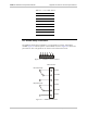
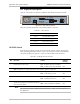
Figure B-2 shows the rear panels of ASMi-52 with the IR-IP interface module.
CONTROL
ALARM
LINE
B
LINE
A
1425
ACTLINK
A
CT
LINK
ERR
SETUP
1234
IR-IP
E1/T1 SHDSL
TX RX
1425
Figure B-2. IR-IP Ethernet Router
Table B-1 provides the pinout of the 10BaseT RJ-45 connector.
Table B-1. RJ-45 Pinout
Pin Name Function
1 TD (+) Transmit data positive
2 TD (-) Transmit data negative
3 RD (+) Receive data positive
6 RD (-) Receive data negative
IR-IP DIP Switch
IR-IP interface module contains a four-section DIP switch, used to configure the
basic operating parameters of the IP router. The switch is located on the ASMi-52
rear panel as shown in Figure B-2. Table B-2 lists the DIP switch functions.
Table B-2. IR-IP DIP Switch Functions
No Function Values Default
Setting
1 Enables IR-IP to learn its IP ON – IP address learning is enabled
OFF – IP address learning is disabled
OFF
Note: For details, see Assigning the Router LAN Interface Address on page B-8.
2 Selects the WAN protocol ON – PPP protocol
OFF – Frame Relay protocol
OFF
3 Selects the LAN mode ON – Full duplex operation
OFF – Half duplex operation
OFF
4 Controls the remote WAN test loopback,
which returns packets received from the WAN
back toward the WAN
ON – The test loopback is activated
OFF – The test loopback is disabled
OFF
The switch can perform additional control functions, which are described below in
this appendix.
Note