
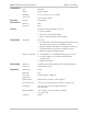
Specifications

Chapter 1 Introduction ASMi-52 Installation and Operation Manual
1-6 Physical Description
Diagnostics
ASMi-52 supports activation of the following:
• Local loopback
• Remote loopback
• Remote loopback at SHDSL repeater (activated from the local unit).
All tests can be activated from the local unit or from the remote unit.
Real time alarms provide information on the system status, indicating management
failure, synchronization loss and other conditions.
Statistic Collection
ASMi-52 supports SHDSL and E1/T1 statistics collection.
Alarm Reporting
ASMi-52 alarms are relayed via dedicated 6-pin terminal block connector.
SHDSL Repeaters
Up to eight SHDSL repeaters can be installed in line to increase the operation
range of the modem. ASMi-52 provides basic management of the repeaters.
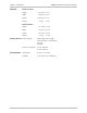
1.2 Physical Description
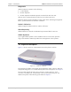
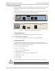
Figure 1-3 shows a 3D view of the ASMi-52 unit in the plastic enclosure.
Figure 1-3. ASMi-52, 3D View
The front panel includes several LEDs, which display the status of power, data flow
and provide diagnostics. For a detailed description of the front panel, see Chapter 3.
The rear panel includes AC/DC power connector, a DTE connector, a line
connector, 10/100BT port, V.24 terminal connector and alarm relay port. The
ASMi-52 rear panel is described in greater detail in Chapter 2.