
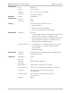
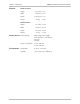
Specifications

ASMi-52 Installation and Operation Manual Chapter 1 Introduction
Functional Description 1-7
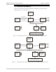
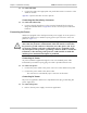
1.3 Functional Description
This section provides a functional description of ASMi-52 in the form of block
diagrams (Figure 1-4 and Figure 1-5).
Modem Glue
Logic
Data & Clock
LEDs and Terminal Interface
Control Signals
CPU
10/100BaseT
Management
Port
CPU Data Bus
DTE
Interface
SHDSL
Line Interface
Power
Supply
Internal
Oscillator
Figure 1-4. ASMi-52/4W with V.35 Interface and 10/100BaseT Management Port
10/100BaseT
Management
Port
Modem Glue
Logic
Data, Clock, Sync
LEDs and Terminal Interface
CPU
CPU Data Bus
DTE
Interface
SHDSL
Line Interface
Internal
Oscillator
Power
Supply
Figure 1-5. ASMi-52/4W with Framed E1 Interface and 10/100BaseT Management Port