
Specifications

Chapter 1 Introduction ASMi-52 Installation and Operation Manual
1-8 Technical Specifications
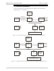
The ASMi-52 modem consists of the following major modules:
DTE interface – Prepares the digital data coming from the DTE into a data stream for the
modem glue logic. In addition it translates the data from the modem glue
logic into digital data to be sent to the DTE.
Internal oscillator – Serves as a source of internal clock for the ASMi-52 unit.
Modem glue logic module – Processes the data from/to the SHDSL interface module.
SHDSL line interface – Translates the received and transmitted data from the line to the
DTE interface.
Power supply – Provides 2.5V, 3.3V, 5V and -5V voltage to the ASMi-52 internal
elements.
CPU – Controls the ASMi-52 operation.
10/100BaseT management port – Provides LAN connection to the SNMP management
station or Telnet host.
LEDs and terminal interface – Provides modem status information via LED indicators on
the front panel, and communicates with the supervisory terminal.
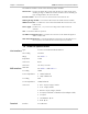
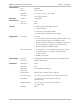
1.4 Technical Specifications
Line Interface
Type
2/4-wire unconditioned dedicated line
Line Coding
TC-PAM
Range
See Table 1-1
Impedance
135Ω
Connector
RJ-45
Protection
ITU K.21, UL1950
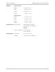
DTE Interface
Data Rate
See Table 1-2 and Table 1-3
E1 Coding
HDB3
E1 Line Impedance
• 120Ω, balanced
• 75Ω, unbalanced
T1 Coding
AMI
T1 Line Impedance
100Ω, balanced
Connector
• X.21: 15-pin, D-type, female
• V.35: 34-pin, female
• RS-530: 25-pin, D-type, female
• E1: RJ-45, balanced or unbalanced (via adapter cable)
• T1: RJ-45
• 10/100BaseT: RJ-45
• IR-IP: RJ-45
Terminal
Interface
V.24 (RS-232)