
Specifications

ASMi-52 Installation and Operation Manual Chapter 2 Installation and Setup
Installation and Setup 2-3
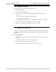
Connecting the Interfaces
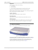
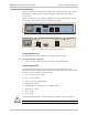
Figure 2-1 illustrates the rear panel of ASMi-52 in a plastic enclosure with a 4-wire
line interface, E1 DTE interface, user LAN interface, alarm relay port and the
control port.
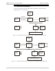
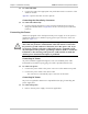
Figure 2-2 illustrates the rear panel of ASMi-52 in a metal enclosure with a 4-wire
line interface, the user LAN interface, and the control port.
E1/T1 SHDSL
DCE
V.35
CONTROL
ALARM
LINE
B
TX
LINE
A
RX
11442255
ACTLINK
Figure 2-1. ASMi-52 Rear Panel (Plastic Enclosure)
SHDSL
CONTROL
LINE
B
LINE
A
1425
ACTLINK
Figure 2-2. ASMi-52 Rear Panel (Metal Enclosure)
Connecting the Line
The ASMi-52 line interface terminates in an 8-pin RJ-45 connector.
To connect the line connector:
• Connect the line cable to the RJ-45 connector designated SHDSL.
Connecting the DTE
The ASMi-52 DTE interface provides interface for input/output data, clock
reference and control signals between the modem and the DTE. The DTE interface
terminates in one of the following connectors:
• X.21 – 15-pin, D-type, female
• V.35 – 34-pin, female
• RS-530 – 25-pin, D-type, female
• Balanced E1 – RJ-45
• Unbalanced E1 – two BNC coax via adapter cable
• Balanced T1 – RJ-45
• IR-IP – RJ-45
• ETH – RJ-45.
For the detailed description of the IR-IP interface module, refer to Appendix B.
The E1/T1 port is intended for intra-building non-exposed plant only.
Warning