
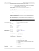
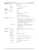
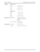
Specifications

Chapter 2 Installation and Setup ASMi-52 Installation and Operation Manual
2-4 Installation and Setup
To connect the DTE:
• Connect the DTE to the appropriate rear panel DTE interface connector of the
ASMi-52 modem.
Appendix A specifies the DTE connector pinouts.
Connecting the Alarm Relay Connector
To connect the alarm relay:
• Connect external alarm device to the rear panel terminal block connector
designated ALARM. Refer to Appendix A for the connector pinout and alarm
functions.
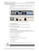
Connecting the Power
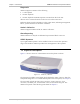
ASMi-52 is equipped with a dual input AC/DC power supply. AC or DC power is
supplied to ASMi-52 via a standard 3-prong power input connector on the rear
panel (see Figure 2-1).
Before connecting this unit to power and connecting or disconnecting any
other cable, the protective earth terminals of this unit must be connected to
the protective ground conductor of the mains (AC or DC) power cord. If you
are using an extension cord (power cable) make sure it is grounded as well.
Any interruption of the protective (grounding) conductor (inside or outside the
instrument) or disconnecting of the protective earth terminal can make this
unit dangerous. Intentional interruption is prohibited.
Connecting AC Power
AC power should be supplied through the 1.5m (5 ft) standard power cable
terminated by a standard 3-prong plug. The cable is provided with the unit.
To connect AC power:
1. Connect the power cable to the power connector on the ASMi-52 rear panel.
2. Connect the power cable to the mains outlet.
The unit turns on automatically upon connection to the mains.
Connecting DC Power
DC power is supplied to ASMi-52 via compatible AC/DC plug for attaching DC
power supply lines.
To connect DC power:
• Refer to the DC power supply connection supplement.
Warning