
Specifications


Indicators 3-1
Chapter 3
Operation
This chapter provides the following information for the ASMi-52 modem:
• ASMi-52 front-panel indicators
• Operating procedures (turn-on, front-panel indications, performance
monitoring and turn-off).
• ASMi-52 default settings.
Installation procedures given in Chapter 2 must be completed and checked before
attempting to operate ASMi-52.
3.1 Indicators
The front and rear panels of ASMi-52 include a series of LED indicators that show
the current operating status of the unit.
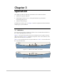
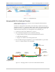
Figure 3-1 shows the front panel of the 2-wire ASMi-52 unit in a plastic enclosure
with an E1 interface. Figure 3-2 illustrates front panel of the 4-wire ASMi-52 unit a
plastic enclosure with a V.35 interface.
Table 3-1 lists and describes the front panel indicators. Table 3-2 lists and describes
the rear panel indicators
ASMi-52
Figure 3-1. ASMi-52 Front Panel, E1 Interface
ASMi-52
Figure 3-2. ASMi-52 Front Panel, V.35 Interface