
Specifications


Chapter 3 Operation ASMi-52 Installation and Operation Manual
3-2 Operating ASMi-52
Table 3-1. ASMi-52 Front Panel LEDs
Name Function
PWR (green) On – Power is ON
TST (red) On – A loopback test is active in local or remote unit
SYNC A
(red/green)
On (red) – Link A is not synchronized
On (green) – Link A is synchronized
Blinks – The line is connected properly and the
synchronization process is taking place
SYNC B
(red/green)
On (red) – Link B is not synchronized
On (green) – Link B is synchronized
Blinking – The line B is connected properly and the
synchronization process is taking place
AIS (yellow) On – “All 1s string” is received at the E1 interface
YELLOW (yellow) On – “All 1s string” is received at the T1 interface
E1/T1 SYNC (red) On – Loss of E1 or T1 synchronization
DATA (yellow) Blinking – Data is being transferred
ALM (red) On – An alarm enters the buffer of local or remote unit
Table 3-2. ASMi-52 Rear Panel LEDs
Name Function
ACT (yellow) Blinks according to Ethernet traffic activity (10/100BaseT
connector)
LINK (green) On – Good link integrity (10/100BaseT connector)
3.2 Operating ASMi-52
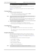
Turning On ASMi-52
To turn on ASMi-52:
• Connect the power cord to the mains.
The PWR indicator lights up and remains lit as long as ASMi-52 receives
power.
ASMi-52 requires no operator attention once installed, with the exception of
occasional monitoring of front panel indicators. Intervention is only required when
ASMi-52 must be configured to its operational requirements, or diagnostic tests are
performed.