RADview-TDM Element Management System for TDM Applications FCD-IP © 1994–2004 RAD Data Communications Publication 12/04
Contents Chapter 1. Introduction 1.1 1.2 1.3 1.4 1.5 Overview..................................................................................................................... 1-1 Introducing RADview FCD-IP ...................................................................................... 1-1 The FCD-IP Workplace................................................................................................ 1-2 Edit and Agent Views ....................................................................
Table of Contents 3.4 Configuring Protocol Parameters................................................................................ 3-29 Configuring Frame Relay Protocol Parameters ..................................................................... 3-29 Configuring the DLCI Table................................................................................................. 3-30 Configuring PPP Parameters ................................................................................................
Table of Contents List of Figures 1-1. FCD-IP Main Window........................................................................................................... 1-2 1-2. Password Dialog .................................................................................................................... 1-3 2-1. FCD-IP Main Window........................................................................................................... 2-1 2-2. System Information .........................................
Table of Contents 3-20. FR Parameters ................................................................................................................... 3-29 3-21. DLCI Table........................................................................................................................ 3-31 3-22. Add DLCI .......................................................................................................................... 3-32 3-23. PPP Protocol ................................................
Table of Contents List of Tables 1-1. FCD-IP LEDs ......................................................................................................................... 1-3 2-1. System Information Parameters ............................................................................................. 2-2 2-2. Static Forwarding Table Parameters ....................................................................................... 2-4 2-3. IP Forwarding Parameters.........................................
Table of Contents 5-1. 5-2. 5-3. 5-4. 5-5. 5-6. 5-7. 5-8. Testing Parameters – E1/T1.................................................................................................... 5-3 Link Statistic Parameters ........................................................................................................ 5-4 Link Statistic Parameters ........................................................................................................ 5-6 FR Error Statistics Parameters ....................
Chapter 1 Introduction 1.1 Overview This chapter describes the RADview management application for FCD-IP, and includes the following sections: • Introducing RADview FCD-IP • The FCD-IP Workplace. 1.2 Introducing RADview FCD-IP RADview FCD-IP enables you to monitor and manage FCD-IP. FCD-IP is an E1/T1 or E1/T1 over SHDSL, fractional integrated access device (IAD), which enables service providers to bundle data, voice and IP access services over a single E1 or T1 access line.
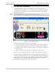
RADview FCD-IP User’s Manual Chapter 1 Introduction 1.3 The FCD-IP Workplace The RADview FCD-IP main window displays FCD-IP front and back panels, including all LEDs and interfaces. You can select most of the displayed interfaces in each section, or select the entire device for system configuration. A blue border marks the selected item. Note To select the device itself, click on any area outside of the ports. Figure 1-1.
RADview FCD-IP User’s Manual Chapter 1 Introduction 1.4 Edit and Agent Views Note Certain TDM ports can be displayed in both Edit and Agent Views. Configuration is performed in the Edit mode. In Agent View, the parameters are Read-Only. To switch between Edit and Agent views: 1. Select the appropriate Link. 2. Switch the view by doing one of the following: Click the Edit/Agent View button on the toolbar or From the Window menu, select Edit View/Agent View to switch to Edit/Agent View. 3.
RADview FCD-IP User’s Manual Chapter 1 Introduction Table 1-1. FCD-IP LEDs (Cont.) Object Description Function LINK1 ERR LINK2 ERR Red LED OFF when there is a physical connection and no LINK interface error. Turns ON briefly when the LINK interface indicates an error. Continuously ON when there is no physical connection. LAN 1 LAN 2 (Back Panel, UTP only) Green LED ON when synchronized with the network.
RADview FCD-IP User’s Manual Chapter 1 Introduction Table 1-1. FCD-IP LEDs (Cont.) Object Description Function SYNCH LOSS LINK1 LOC SUB1/LINK2 LOC SUB2 LOC SUB3 LOC Red LED ON when E1 link is in local sync loss alarm.
Chapter 1 Introduction 1-6 LEDs RADview FCD-IP User’s Manual
Chapter 2 System Management This chapter discusses how to monitor and configure the FCD-IP system. Managing the FCD-IP system includes the following tasks: • Selecting the System Level • Viewing and Modifying FCD-IP System Configuration • Setting Bridging Parameters • Routing the IP • Viewing the Connection Status • Configuring the Dynamic Host Configuration Protocol (DHCP) • Resetting the Device • Polling the Agent • Configuring SNMP • Switching Between Edit and Agent View. 2.
RADview FCD-IP User’s Manual Chapter 2 System Management 2.2 Viewing and Modifying System Configuration RADview enables you to view and modify the configuration of the FCD-IP. To view or modify FCD-IP system information: 1. Select Configuration > System Info... or click the shortcut key on the toolbar . The System Information dialog box appears (See figure below). Figure 2-2. System Information 2. Enter the required settings.
RADview FCD-IP User’s Manual Chapter 2 System Management Table 2-1. System Information Parameters (Cont.) Parameter Possible Values / Remarks System Up Time Length of time since last power-up of device. Aging (Min) IP aging time for the station. Enable Broadcast Control Enables blocking or forwarding broadcast frames. Block: blocks broadcast frames. Forward: forwards broadcast frames. Block Link Propagation: blocks broadcast frames to the links, transmitting to the LAN.
RADview FCD-IP User’s Manual Chapter 2 System Management Table 2-2. Static Forwarding Table Parameters Parameter Possible Values / Remarks MAC Address The physical address of the device. Interface The selected interface. DLCI# Data Link Control Identifier Only for links with FR protocol type. [Add…] Click to open the Add IP Net Entry dialog box (Figure 2-4). Enter the desired parameters and click .
RADview FCD-IP User’s Manual Chapter 2 System Management 2.4 Routing the IP Forwarding Table To display the IP Forwarding Table: • Select Configuration > IP Routing > Forwarding.... The IP Forwarding Table appears (Figure 2-5). Figure 2-5.
RADview FCD-IP User’s Manual Chapter 2 System Management Table 2-3. IP Forwarding Parameters Parameter Possible Values / Remarks IP Address The IP address of forwarding device. IP Mask A unique 32 bit value allowing the recipient of IP packets to distinguish between different host IDs. Next Hop IP Address The IP address of the next hop. Interface The selected interface. DLCI# Data Link Control Identifier Only for links with FR protocol type.
RADview FCD-IP User’s Manual Chapter 2 System Management Address Resolution Protocol Table To display the ARP table: • Select Configuration > IP Routing > ARP.... The ARP Stations Table appears (Figure 2-6). Figure 2-6. ARP Stations Table Table 2-4. ARP Stations Parameters Parameter Possible Values / Remarks Interface The selected interface. MAC Address The physical address of the device. Net Address The IP address of the MAC Address.
RADview FCD-IP User’s Manual Chapter 2 System Management IP Address Table To display the IP address table: • Select Configuration > IP Routing > IP Address.... The IP Addresses Table appears (Figure 2-7). Figure 2-7. IP Addresses Table Table 2-5. IP Address Parameters Parameter Possible Values / Remarks IP Address The IP address of forwarding device. 1.0.0.0..255.255.255.255 IP Mask A unique 32 bit value allowing the recipient of IP packets to distinguish between different host IDs. 0.0.0.0..255.
RADview FCD-IP User’s Manual Chapter 2 System Management To add an IP address: 1. In the IP Address Table (Figure 2-7), click . The Add IP Address dialog box appears (Figure 2-8). Figure 2-8. Add IP Address Note When working in OSPF mode, each LAN can have only one IP address. 2. Configure desired parameters (see Table 2-3). 3. Click . To change an IP address: 1. In the IP Address Table (Figure 2-7), click . The Change IP Address dialog box appears (Figure 2-9). Figure 2-9.
RADview FCD-IP User’s Manual Chapter 2 System Management 2.5 OSPF RADview allows you to configure OSPF and view OSPF information. Configuring OSPF To enable OSPF: 1. Select Configuration > OSPF > Parameters…. The OSPF Parameters dialog box appears. Figure 2-10. OSPF Parameters (Enable) 2. In the Admin Status field, select Enable. 3. Enter the Router ID. 4. Enable or disable Redistribute Routes. 5. Click to implement the changes.
RADview FCD-IP User’s Manual Chapter 2 System Management To disable OSPF: 1. Select Configuration > OSPF > Parameters…. The OSPF Parameters dialog box appears. Figure 2-11. OSPF Parameters (Disable) 2. In the Admin Status field, select Disable. 3. Click to implement the changes. The following confirmation message appears: “This operation will cause Restart of the device /n Connection with Agent will be lost.” 4. Click . Table 2-6.
RADview FCD-IP User’s Manual Chapter 2 System Management OSPF Areas To display the OSPF Area Table: • Select Configuration > OSPF > Area Table.... The OSPF Area Table appears. Figure 2-12. OSPF Area Table Table 2-7 OSPF Area Table Parameters Parameter Possible Values / Remarks ID The IP address of the area. 1.0.0.0..255.255.255.255 Behavior Type Transit, Stub, NSSA [Change…] Change an OSFP Area behavior by selecting an ID and clicking . The Change Area Parameters dialog box appears.
RADview FCD-IP User’s Manual Chapter 2 System Management Figure 2-13. OSPF Area Aggregation Table Table 2-8 OSPF Area Aggregation Parameters Parameter Possible Values / Remarks Area The ID of the area. 1.0.0.0..255.255.255.255 IP The IP address of the network. 1.0.0.0..255.255.255.255 Mask A unique 32 bit value allowing the recipient of IP packets to distinguish between different host IDs. 0.0.0.0..255.255.255.255 Advertised Advertising matching is enabled/disabled.
RADview FCD-IP User’s Manual Chapter 2 System Management To add an Area Aggregation entry: 1. In the Area Aggregation Table, click . The Add Area Aggregation dialog box appears. Figure 2-14. Add Area Aggregation 2. Configure desired parameters (see Table 2-8). 3. Click . (Clicking performs Set operation without closing dialog box.) 4. When all entries have been added, click . The Add Area Aggregation dialog box closes and all added entries appear at the end of the list.
RADview FCD-IP User’s Manual Chapter 2 System Management OSPF Interfaces Information To display the OSPF Interfaces table: • Select Configuration > OSPF > Information > Interfaces.... The Interfaces Table appears. Figure 2-15. Interfaces Table Table 2-9. Interfaces Parameters Parameter Possible Values / Remarks IP Address/Interface The IP address or the link number of the interface. Area ID The IP address associated with the area.
RADview FCD-IP User’s Manual Chapter 2 System Management Figure 2-16. Neighbors Table Table 2-10. Neighbors Parameters Parameter Possible Values / Remarks IP Address/Interface The IP address or the link number of the interface. Router ID The IP address of the relevant router. Priority The interface priority.
RADview FCD-IP User’s Manual Chapter 2 System Management OSPF Database Information To display the OSPF Database table: • Select Configuration > OSPF > Information > Database.... The Database Table appears. Figure 2-17. Database Table Table 2-11. Database Parameters Parameter Possible Values / Remarks Area ID The IP address associated with the area. DB Type Link Router, Network, Summary, AS Summary, AS External, Multicast, NSSA External Link State ID The IP address format.
RADview FCD-IP User’s Manual Chapter 2 System Management 2.6 Viewing the Connection Status RADview enables you to view the list of all the logical links related to the physical links of the device. To display the connection status of the device: • Select Configuration > Connection Status... The All Links Connections list appears (Figure 2-18). Figure 2-18. All Links Connections List Table 2-12. All Links Connections Parameters Parameter Possible Values / Remarks Interface The selected interface.
RADview FCD-IP User’s Manual Chapter 2 System Management 2.7 Configuring the Dynamic Host Configuration Protocol (DHCP) RADView enables you to configure the Dynamic Host Configuration Protocol (DHCP). To display the DHCP: • Select Configuration > System Commands > DHCP… The DHCP table appears (Figure 2-19). Figure 2-19. Dynamic Host Configuration Protocol Table Table 2-13.
RADview FCD-IP User’s Manual Chapter 2 System Management Table 2-13. Dynamic Host Configuration Protocol Parameters (Cont.) Parameter Possible Values / Remarks Interface The interface through which the remote interface of the IP address is received. All, LAN1, LAN2, Any LAN, WAN [Apply] To save changes in table, click . [Add…] To add an entry to the table, click . Configure the parameters in the Add DHCP Entry table and click . A maximimum of 10 entries is allowed in the table.
RADview FCD-IP User’s Manual Chapter 2 System Management Figure 2-21. Change DHCP Entry 2. Configure desired parameters (see Table 2-13). 3. Click . The Add DHCP Entry dialog box closes. 2.8 Resetting the Device RADview enables you to reset the device. To reset the device: 1. Select Configuration > System Commands > Reset… or click the shortcut key on the toolbar . The following message appears: “RESETTING BROUTER. Operation may disrupt network data.” Figure 2-22. Reset Brouter 2.
RADview FCD-IP User’s Manual Chapter 2 System Management 2.9 Polling the Agent RADview allows you to poll the FCD-IP device. To poll the agent: • Select Configuration > Poll Agent or click the shortcut key on the toolbar . The system polls the agent immediately. 2.10 Configuring SNMP RADview enables you to view and modify SNMP settings; enabling you to specify management stations that can receive FCD-IP traps.
RADview FCD-IP User’s Manual Chapter 2 System Management 2. Configure the IP Address for the different managers. 3. Click . Table 2-14. Manager List Parameters Parameter Possible Values / Remarks Manager ID The ID number of the manager. IP Address The IP address of the manager. 2.11 Switching Between Edit and Agent View The device is managed with two different community views: one for the TDM scope, and one for the rest of the parameters.
Chapter 2 System Management 2-24 Switching Between Edit and Agent View RADview FCD-IP User’s Manual
Chapter 3 Port Management This chapter describes RADview’s configuration and operation procedures for the FCD-IP LINK and LAN. The LINK or LAN Level is available when a LINK or LAN is selected. Some LINKS have both edit and agent levels. This chapter details the different management options for each LINK and LAN separately. 3.1 Edit and Agent Views Note Certain TDM ports can be displayed in both Edit and Agent Views. Configuration is performed in the Edit mode. In Agent View, the parameters are Read-Only.
RADview FCD-IP User’s Manual Chapter 3 Port Management To configure interface information: 1. Select a Link or Channel. The Agent view is displayed for the selected object. 2. Select Configuration > Interface Info… The Interface Information dialog box appears. There are two tabs: Info and Link Data. Figure 3-1. Interface Information Info Tab 3. Click on the required tab. 4. Configure the desired parameters. 5. Click . Table 3-1.
RADview FCD-IP User’s Manual Chapter 3 Port Management Figure 3-2. Interface Information Link Data Tab Notes • Link Data tab is disabled for Sub and Voice links. • Changing the protocol type from Frame Relay (RFC 1490) to any other protocol will cause the device to reset. The following message appears “This operation will cause HW reset of the Device. Continue?” Click to confirm reset. Table 3-2.
Chapter 3 Port Management RADview FCD-IP User’s Manual Table 3-2 Interface Information Link Data Tab Parameters (Cont.) Parameter Possible Values / Remarks Routing / Bridging (not available for the SUB LINK or CHANNEL) Bridge, IP Router, IPX Router, IP and IPX Router, IP Brouter, IPX Brouter, IP and IPX Brouter IP Transparent Mode Enables/disables IP transparent mode.
RADview FCD-IP User’s Manual Chapter 3 Port Management Table 3-3. Info Tab Parameters for SHDSL Parameter Possible Values / Remarks Interface The selected interface. Type The type of interface. SHDSL Description Description of the selected interface. Oper Status The operational status of link. Up, Down MTU The maximum Transmit Unit for IP fragmentation.
RADview FCD-IP User’s Manual Chapter 3 Port Management Configuring E1/T1 over SHDSL Interface Information This section describes how to view and configure E1/T1 over SHDSL interface information. Note For information on E1/T1 interfaces that are not over SHDSL, see Configuring E1/T1, CHANNEL, ISDN, and Voice Interface Information. To configure interface information: 1. Select a Link or Channel. 2. Select Configuration > Interface Info… The Interface Information dialog box appears.
RADview FCD-IP User’s Manual Chapter 3 Port Management Figure 3-4. Interface Information Link Data Tab for E1/T1 over SHDSL 3. Click on the required tab. 4. Configure the desired parameters. 5. Click . Table 3-5. Info Tab Parameters for E1/T1 over SHDSL Parameter Possible Values / Remarks Interface The selected interface. Description Description of the selected interface. Oper Status The operational status of link. Up, Down MTU The maximum Transmit Unit for IP fragmentation.
Chapter 3 Port Management RADview FCD-IP User’s Manual Table 3-6. Interface Information Link Data Tab Parameters for E1/T1 over SHDSL Parameter Possible Values / Remarks Interface The selected interface. State Enable, Disable, Backup (only if there is more than one link) Backup of Link The combo box listing links in current configuration.
RADview FCD-IP User’s Manual Chapter 3 Port Management Configuring LAN Interface Information To configure interface information for an Ethernet LAN: 1. Select the desired Ethernet LAN. 2. Select Configuration > Interface Info… The Interface Information dialog box appears. Figure 3-5. Interface Information – Ethernet LAN Note Changing the values for Burn In MAC or Locally Administered will cause disconnection with the agent. Table 3-7.
RADview FCD-IP User’s Manual Chapter 3 Port Management Table 3-7. Interface Information – Ethernet LAN Parameters (Cont.) Parameter Possible Values / Remarks Active Address Burn In MAC Changing this parameter will cause disconnection with the agent. Locally Administered Changing this parameter will cause disconnection with the agent. LAN State Enable, Disable Selecting Disable for this parameter will cause disconnection with the agent.
RADview FCD-IP User’s Manual Chapter 3 Port Management Figure 3-6. Async Link Parameters Dialog Box Table 3-8. Async Link Parameters Parameter Possible Values / Remarks Interface LINK1, LINK2 Rate (Kbps) 2.4, 4.8, 9.6, 19.2, 38.4, 57.6, 115.
RADview FCD-IP User’s Manual Chapter 3 Port Management Table 3-8. Async Link Parameters (Cont.) Parameter Possible Values / Remarks Local Number Maximum 40 characters. Valid characters are: 0..9, P, T, W , ', @ Number of rings before answer 1..2..255 [Add Modem…] Click to open the Add Modem dialog box (Figure 3-7). Enter the desired parameters and click . [Remove Modem] Remove a modem by selecting a modem from the Modem Name drop-down list and clicking .
RADview FCD-IP User’s Manual Chapter 3 Port Management Configuring ISDN Physical Parameters To configure ISDN physical parameters: 1. Select the ISDN Link. 2. Select Configuration >Physical Parameters… The ISDN dialog box appears. 3. Click on the desired tab and configure desired parameters. 4. Click . Figure 3-8. ISDN Parameters – Interface Tab Table 3-10.
RADview FCD-IP User’s Manual Chapter 3 Port Management Figure 3-9. ISDN Parameters – Terminal End Point Tab Table 3-11. ISDN Parameters – Terminal End Point Tab Parameter Possible Values / Remarks Interface LINK1, LINK2 ETSI Abstract Terminal 1 Terminal Index The Terminal Index. Service Provider ID (SPID) The Service Provider ID . Up to 20 digits Directory Number The Directory Number. Up to 18 digits TEI Management Dynamic, Static TEI Value 0..
RADview FCD-IP User’s Manual Chapter 3 Port Management Figure 3-10. ISDN Parameters - Channel Tab Table 3-12. ISDN Parameters - Channel Tab Parameter Possible Values / Remarks Interface The selected interface. Calling Number The Calling Number. Up to 18 digits Calling Sub-Number The Calling Sub-Numbe.r Up to 6 digits Called Phone Number The Called Phone Number. Up to 18 digits Called Sub-Number The Called Sub-Number.
RADview FCD-IP User’s Manual Chapter 3 Port Management Configuring E1/T1 Link Mode Notes • Link mode configuration is available for Main E1/T1 link for devices having two E1/T1 ports. • Note that, while the link mode can be configured only in the Edit View, switching traffic between links can only be performed in Agent mode, which detects the actual current mode of the link. To configure E1/T1 link mode: 1. Select Link1. 2. Select Configuration >Physical Parameters > Mode….
RADview FCD-IP User’s Manual Chapter 3 Port Management Configuring General E1/T1 Physical Parameters To configure E1/T1 general physical parameters: 1. Select an E1/T1 Link or Channel. 2. Select Configuration > Physical Parameters > General…. The E1/T1 Link Parameters dialog box appears. Figure 3-12. General Link Parameters (E1/T1 Ports) Table 3-14. General Link Parameters (E1/T1 Ports) Parameter Possible Values / Remarks Interface The selected interface.
Chapter 3 Port Management RADview FCD-IP User’s Manual Table 3-14. General Link Parameters (E1/T1 Ports) (Cont.) Parameter Possible Values / Remarks Multiplier (Kbps) The data rate of each DATA time slot. 56, 64 Note: This parameter is only enabled for the main link only. T1: ESF (24 frames per multiframe), D4 (12 frames per multiframe). Line Type E1: E1 (G732N-2 frames per multiframe), - CCITT Rec. G.704 - Table 4a E1-CRC (G732NCRC), - CCITT Rec. G.704 - Table 4b E1-MF - CCITT Rec. G.
RADview FCD-IP User’s Manual Chapter 3 Port Management Table 3-14. General Link Parameters (E1/T1 Ports) (Cont.) Parameter Possible Values / Remarks RAI The Remote Alarm Indication (for main links with sub links). Off, On For main links: On transmits a yellow alarm indication on the E1 sub link when Link 1 is in yellow alarm state . For Sub links: On transmits a yellow alarm indication on Link 1 when sub link E1 is in either yellow or red alarm state.
RADview FCD-IP User’s Manual Chapter 3 Port Management MAIN E1 1 2 3 4 5 21 DATA 1 +2 23 24 D D 30 31 D D D SUB1/ LINK 2 VOICE 1 22 D D V VOICE 2 V VOICE 3 VOICE 4 Figure 3-14. TS Assignment (New HW) A rectangular grid displays the time slot assignments. Each row and each column represents the possible connections of a specific port. Since all ports are connected to MAIN E1/T1 port, the top row shows the TS assignments of the MAIN E1/T1. For the MAIN E1, there are 31 Time Slots.
RADview FCD-IP User’s Manual Chapter 3 Port Management TS Letter Codes The connection cells use letter codes to describe the type of the connected time slots. D Data V Voice Port Name Color Codes Green All of the port's connectable TS connections are connected. Gray None of the port's connectable TSs are being used. Yellow Some of the ports have TS connections. This is valid for the MAIN or SUB ports only. Selecting a Port Cell To select a cell: • Click on the desired cell.
RADview FCD-IP User’s Manual Chapter 3 Port Management Exiting the TS Assignment Window To exit the TS Assignment window: • Double-click the control box in the upper left corner of the window or click on the X in the upper right-hand side of the window. Reading the E1/T1 Configuration from the Agent Note Read is only available for TDM ports in Edit View. RADview enables you to upload the current Agent configuration to the Edit Configuration mode.
RADview FCD-IP User’s Manual Chapter 3 Port Management Figure 3-16. Update Configuration 4. Click to update the configuration. To abort the Update operation: • Click . Configuring SHDSL Physical Parameters To configure SHDSL physical parameters: 1. Select a SHDSL Link. 2. Select Configuration > Physical Parameters > SHDSL > Parameters… The SHDSL Link Parameters dialog box appears. 3. Configure the desired parameters. 4. Click .
RADview FCD-IP User’s Manual Chapter 3 Port Management Figure 3-17. SHDSL Parameters Table 3-15. SHDSL Parameters Parameter Possible Values / Remarks Interface LINK 1 Type SHDSL Transmission Mode Annex A, Annex B Power Specral Density Symmetric, Asymmetric (PSD) Mask Asymmetric PSD Rate R1, R2 (only when PSD=Asymmetric) Selected rate depends on transmission mode specified in Annex A or B of G.991.
RADview FCD-IP User’s Manual Chapter 3 Port Management Table 3-15. SHDSL Parameters (Cont.) Parameter Possible Values / Remarks Wire Interface 2 Wire, 4 Wire Rate Mode Fixed, Adaptive SNR Startup Margin Specifies the downstream current condition target SNR margin for a SHDSL line. The SNR margin is the difference between the desired SNR and the actual SNR. Target SNR margin is the desired SNR margin for a unit. -10..
RADview FCD-IP User’s Manual Chapter 3 Port Management Table 3-16. SHDSL Status Parameters Parameter Possible Values / Remarks Actual Rate (Kbps) Contains the actual line rate in this HDSL2/SHDSL span. 192…4608 Loop Attenuation (dB) Current loop attenuation for this endpoint as reported in a Network or Customer Side Performance Status message. -127…128 SNR Margin (dB) Current SNR margin for this endpoint as reported in a Status Response/SNR message.
RADview FCD-IP User’s Manual Chapter 3 Port Management Table 3-17. Voice Parameters (Cont.) Parameter Possible Values / Remarks Tx Gain (dBm) The transmit gain in dBm. -10, -8, -6, -4, -2, 0, 2, 4, 5 Rx Gain (dBm) The receive gain in dBm. -10, -8, -6, -4, -2, 0, 2, 4, 5 Coding Law Indicates the Method/Law for decoding/encoding the voice information.
RADview FCD-IP User’s Manual Chapter 3 Port Management Table 3-17. Voice Parameters (Cont.
RADview FCD-IP User’s Manual Chapter 3 Port Management 3.4 Configuring Protocol Parameters RADview enables you to configure parameters for the different protocols. Table 3-18.
RADview FCD-IP User’s Manual Chapter 3 Port Management Table 3-19. FR Parameters Parameter Possible Values / Remarks Port Interface The selected interface. DLCI / Maintenance Self Learning Specifies whether device self learns maintenance protocol on FR link and the existing DLCIs and staus of the existing DLCIs (Up or Down). On, Off When Off, maintenance protocol and DLCI must be configured manually. Maintenance Protocol Specifies maintenance protocol of the FR link.
RADview FCD-IP User’s Manual Chapter 3 Port Management Figure 3-21. DLCI Table Table 3-20. DLCI Table Parameters Parameter Possible Values / Remarks Interface The selected interface. DLCI # Specifies DLCI number. State Specifies state of DLCI. Active, Inactive (for receive/transmit) CIR Value Specifies maximum number of data bits that the network guarantees to transfer during the measurement interval.
RADview FCD-IP User’s Manual Chapter 3 Port Management Figure 3-22. Add DLCI To remove an entry from the DLCI Table: 1. In the DLCI Table, select an entry. 2. Click < Remove>. Configuring PPP Parameters To configure PPP parameters: 1. Select a Link or Channel. 2. Select a port where the Protocol Type (see Protocol Type) has been defined as PPP. 3. Select Configuration > Protocols > PPP… The PPP Protocol Parameters dialog box appears. Figure 3-23.
RADview FCD-IP User’s Manual Chapter 3 Port Management Table 3-21. PPP Protocol Parameters Parameter Possible Values / Remarks Interface The selected interface. For ISDN the parameters will appear on two tabs: Channel 1 and Channel 2. Bad Controls The number of packets received on this link with an incorrect control field. Bad FCSs The number of received packets that have been discarded due to having an incorrect FCS.
RADview FCD-IP User’s Manual Chapter 3 Port Management 3.5 Configuring Network Parameters RADview enables you to set IP addresses, IP routing protocol and DHCP Relay parameters for the selected interface or DLCI. Configuring IP Addresses To set an IP Address: 1. Select the required interface. 2. Select Configuration >Network Parameters > IP Addresses… The IP Address Table dialog box appears. The IP Address Table dialog box varies depending on the selected link or DLCI.
RADview FCD-IP User’s Manual Chapter 3 Port Management Configuring the IP Routing Protocol Configuring the IP routing protocol varies slightly, depending on the software version you are running. The appropriate one of the following two options will appear in the Network Parameters menu: • IP Routing Protocol • IP RIP Mode To set IP Routing Protocol: 1. Select a link in which protocol type is not FR. 2.
RADview FCD-IP User’s Manual Chapter 3 Port Management Table 3-23. IP Routing Protocol Parameters (Cont.) Parameter Possible Values / Remarks OSPF Area ID The IP address that identifies the OSPF area. […] Opens the Select Area dialog box listing the existing OSPF areas and the behavior type of each area. To select an OSPF area, click<…>. Select the desired area from the listing and click . Priority Hello Interval The interval (in seconds) at which a hello message is transmitted in the area.
RADview FCD-IP User’s Manual Chapter 3 Port Management Configuring DHCP Relay To set DHCP Relay: 1. Select the desired link. 2. Select Configuration >Network Parameters > DHCP Relay… The DHCP Relay Parameters dialog box appears. Figure 3-27. DHCP Relay Parameters Table 3-25. DHCP Relay Parameters Parameter Possible Values / Remarks Interface Link 1, Link 2, Link 3 Description String containing information about the interface.
RADview FCD-IP User’s Manual Chapter 3 Port Management 3.7 Performing Diagnostic Tests RADview enables you to run diagnostic tests for: E1/T1 Link, E1/T1 Sublink, SHDSL, SUB1/ LINK2, SUB 2, SUB 3, Voice Port. Note When configuring TDM (Voice) parameters a password is required. To run diagnostics tests: 1. Select a Link or Channel. 2. Select Diagnostics > Test… The Testing dialog box appears. Figure 3-28. Testing Table 3-26.
Chapter 4 Fault Management This chapter discusses how to manage faults for the FCD-IP system. Managing faults includes the following tasks: • Displaying Sanity Check Errors (E1/T1 Link) • Displaying SHDSL Alarms. 4.1 Edit and Agent Views Note Certain TDM ports can be displayed in both Edit and Agent Views. Configuration is performed in the Edit mode. In Agent View, the parameters are Read-Only. To switch between Edit and Agent views: 1. Select the appropriate Link. 2.
RADview FCD-IP User’s Manual Chapter 4 Fault Management Figure 4-1. Sanity Check Errors List 4.3 Displaying SHDSL Alarms To view SHDSL alarms: 1. Select an SHDSL Link. 2. Select Fault >SHDSL > Alarms… The SHDSL alarms dialog box appears (Figure 4-2). Figure 4-2.
Chapter 5 Performance This chapter discusses how to monitor the performance of the FCD-IP system. Performance monitoring includes the following tasks: • Setting the Polling Interval • Performing Diagnostic Tests • Displaying E1/T1 Statistics • Displaying E1 Over SHDSL Statistics • Displaying Ethernet LAN Statistics. 5.1 Edit and Agent Views Note Certain TDM ports can be displayed in both Edit and Agent Views. Configuration is performed in the Edit mode.
RADview FCD-IP User’s Manual Chapter 5 Performance 5.2 Setting the Polling Interval RADview enables you to set the current statistics polling interval to automate FCD-IP statistics updates, per assigned elapsed time intervals. To set the polling interval: 1. Select a Link or Channel. 2. Select Statistics >Physical Layer > Polling Interval… or Select Statistics >Physical Layer > SHDSL > Polling Interval… The Polling Interval dialog box appears (Figure 5-1). 3.
RADview FCD-IP User’s Manual Chapter 5 Performance Table 5-1. Testing Parameters – E1/T1 Parameter Possible Values / Remarks Interface The selected port. Link1, Link2, Link3, SUB1/Link2, SUB 2, SUB 3, Interface Type The interface type of the selected port. E1/T1 Current Test The currently running test. New Test Remote Digital Loopback (T1 only), Remote Analog Loopback, Local Analog Loopback [Stop Test] Click to stop a currently running test.
RADview FCD-IP User’s Manual Chapter 5 Performance Table 5-2. Link Statistic Parameters Parameter Possible Values / Remarks Interface The selected interface. Packets Rx Unicast Frames The number of subnetwork Unicast packets received froma higher layer protocol. Rx Multicast Frames The number of subnetwork Multicast packets received from a higher layer protocol. Tx Unicast Frames The number of subnetwork Unicast packets transmitted to a higher layer protocol.
RADview FCD-IP User’s Manual Chapter 5 Performance To display link octet statistics in a graph: 1. Select a Link or Channel. 2. Select Statistics >Packets Graph > Octets... The Link Octets graph appears (Figure 5-5). Figure 5-5. Link Octets To display link error frame statistics in a graph: 1. Select a Link or Channel. 2. Select Statistics >Packets Graph > Error Frames... The Link Error Frames graph appears (Figure 5-6). Figure 5-6.
RADview FCD-IP User’s Manual Chapter 5 Performance Physical Layer Statistics RADview enables you to display link statistics about the physical layer of the selected interface. To display physical layer statistics: 1. Select a Link or Channel. 2. Select Statistics >Physical Layer > Current Interval > Table… The E1 Link Statistics dialog box appears (Figure 5-7). Figure 5-7. E1 Link Statistics Table 5-3. Link Statistic Parameters Parameter Possible Values / Remarks Interface The selected interface.
RADview FCD-IP User’s Manual Chapter 5 Performance To display the physical layer statistics in graph form: 1. Select a Link or Channel. 2. Select Statistics >Physical Layer > Current Interval > Graph… The Current Graph dialog box appears (Figure 5-8). Figure 5-8. Current Graph Statistics To display interval statistics for the physical layer: 1. Select a Link or Channel. 2. Select Statistics >Physical Layer > Intervals Data > Table… The Errors Statistics Intervals dialog box appears (Figure 5-9).
RADview FCD-IP User’s Manual Chapter 5 Performance To display the next 20 entries in the table: • Click . To display statistics starting at a specific interval: 1. Select the desired interval from the Starting from Interval list box (upper right hand corner of Error Statistics Intervals dialog box). 2. Click . To display the table data in a graph: 1. Select a Link or Channel. 2.
RADview FCD-IP User’s Manual Chapter 5 Performance Protocol Layer Statistics RADview enables you to display statistics about the protocol layer of the selected interface. Note Protocol Layer statistics are available only for FR ports. To display FR Error statistics: 1. Select a FR port. 2. Select Statistics >Protocol Layer… The FR Error Statistics dialog box appears (Figure 5-11). Figure 5-11.
RADview FCD-IP User’s Manual Chapter 5 Performance Table 5-4. FR Error Statistics Parameters Parameter Possible Values / Remarks Interface The selected interface. Type Displays the type of error. Time The system up time when error was detected. Faults The number of faults that have occurred. Fault Time The time when the error was detected. Data Provides information about the different faults. [DLCI…] Click to view DLCI Statistics dialog box (Figure 5-12).
RADview FCD-IP User’s Manual Chapter 5 Performance Table 5-5. DLCI Statistics Parameters Parameter Possible Values / Remarks Interface The selected interface. DLCI The DLCI value. FECN The number of frames received from the network indicating forward congestion since the virtual circuit was created. BECN The number of frames received from the network indicating backward congestion since the virtual circuit was created.
RADview FCD-IP User’s Manual Chapter 5 Performance 5.5 Displaying E1 Over SHDSL Statistics Physical Layer Statistics To display physical layer statistics: 1. Select a Link or Channel. 2. Select Statistics >SHDSL > Current > 15 min Data… The 15 min, Current Data box appears (Figure 5-13). Figure 5-13. 15 min. Current Data Table 5-6.
RADview FCD-IP User’s Manual Chapter 5 Performance To display the physical layer statistics in graph form: 1. Select a Link or Channel. 2. Select Statistics >SHDSL > Current > 15 min Graph… The 15 min, Current Graph box appears (Figure 5-13). Figure 5-14. 15 min. Current Graph To display interval statistics for one day: 1. Select a Link or Channel. 2. Select Statistics >SHDSL > Current > One Day Data… The 1 Day Current Data dialog box appears (Figure 5-15). Figure 5-15.
RADview FCD-IP User’s Manual Chapter 5 Performance To display interval statistics for the physical layer: 1. Select a Link or Channel. 2. Select Statistics >SHDSL > Intervals > 15 min. Data… The 15 min. Intervals Data dialog box appears (Figure 5-16). Figure 5-16. 15 min. Intervals Data To display the table data in a graph: 1. Select a Link or Channel. 2. Select Statistics >SHDSL > Intervals > 15 min. Graph… The 15 min. Intervals Graph dialog box appears (Figure 5-17). Figure 5-17. 15 min.
RADview FCD-IP User’s Manual Chapter 5 Performance 5.6 Displaying Ethernet LAN Statistics RADview enables you to display general statistics as well as error statistics for the Ethernet LAN interface. To display general statistics for the LAN: 1. Select the Ethernet LAN. 2. Select Statistics >Table > LAN General… The LAN General dialog box appears (Figure 5-18). Figure 5-18. LAN General Table 5-7. LAN General Parameter Possible Values / Remarks Interface The selected interface.
RADview FCD-IP User’s Manual Chapter 5 Performance To display error statistics for the LAN: 1. Select the Ethernet LAN. 2. Select Statistics >Table > Errors… The LAN Errors Statistics dialog box appears (Figure 5-19). Figure 5-19. LAN Errors Statistics Table 5-8. LAN Errors Statistics Parameters Parameter Possible Values / Remarks Interface The selected interface. Error Frames Received Error Frames The number of error frames received.
RADview FCD-IP User’s Manual Chapter 5 Performance Table 5-8. LAN Errors Statistics Parameters (Cont.) Parameter Possible Values / Remarks Tx & Rx Errors Internal Mac Transmit Errors The number of frames for which transmission to selected interface fails due to internat MAC sublayer transmitt error. Internal Mac Receive Errors The number of frames for which transmission to selected interface fails due to internat MAC sublayer receive error.
RADview FCD-IP User’s Manual Chapter 5 Performance Figure 5-20. LAN Packets To display the statistics for the Octets group in a graph: • Select Statistics >Graph > Octets… The LAN Octets dialog box appears (Figure 5-21). Figure 5-21.
RADview FCD-IP User’s Manual Chapter 5 Performance To display the statistics for the Frame Errors group in a graph: • Select Statistics >Graph > Frames Errors… The ETH Error Frames dialog box appears (Figure 5-22). Figure 5-22. ETH Error Frames To display the statistics for the Tx & Rx Errors group in a graph: • Select Statistics >Graph > Tx & Rx Errors… The ETH Tx & Rx Errors dialog box appears (Figure 5-23). Figure 5-23.
RADview FCD-IP User’s Manual Chapter 5 Performance To display the statistics for the FCS & Test Errors group in a graph: • Select Statistics >Graph > FCS & Test Errors… The ETH FCS & Test Errors dialog box appears (Figure 5-24). Figure 5-24. ETH FCS & Test Errors To display the statistics for the Collisions group in a graph: • Select Statistics >Graph > Collisions… The LAN Collisions dialog box appears (Figure 5-25). Figure 5-25.
Chapter 6 Configuring FCD-IP for a Typical Application This chapter provides detailed instructions for configuring a typical FCD-IP application. This application involves configuring: • WAN Interface • E1 Interface • LAN Interface. Each section shows the appropriate interface connections for those applications on the FCD-IP rear panel. 6.
RADview FCD-IP User’s Manual Chapter 6 Configuring FCD-IP for a Typical Application Table 6-1. Configuration Summary WAN Parameters E1 Parameters LAN Host Parameters • Link mode: Synchronous • Master clock: Link 1 • LAN Status: Enable • Routing: IP router • Multiplier: 64 kbps • Host IP address: 192.168.10.2 • Protocol: PPP • Timeslots 1–4: FIX SUB Voice • Host IP mask: 255.255.255.000 • WAN IP address: 192.168.10.1 • Timeslots 5–8: DATA LINK1 • WAN IP mask: 255.255.255.
RADview FCD-IP User’s Manual Chapter 6 Configuring FCD-IP for a Typical Application 5. From the State drop-down list, select Enable. 6. In the Link Type field, type Synchronous. 7. From the Protocol drop-down list, select PPP. 8. From the Routing/Bridging drop-down list, select IP Router. 9. Click . Configuring the WAN IP Address To configure the WAN IP address: 1. Switch to Agent View: Click the Agent View button on the toolbar . 2. Select Configuration > Network Parameters > IP Address....
Chapter 6 Configuring FCD-IP for a Typical Application RADview FCD-IP User’s Manual 4. In the IP Address field, type 192.168.10.1. 5. In the IP Mask field, type 255.255.255.252. 6. In the Interface drop-down list, select LINK1. 7. Click . 6.3 Configuring the E1 Interface Configuring the E1 interface includes the following: • Configuring E1 Parameters • Mapping E1 Timeslots. Configuring E1 Parameters To configure E1 parameters: 1. Select LINK1. 2.
RADview FCD-IP User’s Manual Chapter 6 Configuring FCD-IP for a Typical Application Mapping E1Timeslots To configure TS parameters: 1. Select LINK1. 2. Switch to Edit View: Click the Edit View button on the toolbar . 3. Select Configuration >Physical Parameters > TS Assign… or click the shortcut key on the toolbar . The TS Assignment dialog box appears (Figure 6-6). Figure 6-6. TS Assignment 4.
Chapter 6 Configuring FCD-IP for a Typical Application RADview FCD-IP User’s Manual Figure 6-7. Interface Information - Ethernet LAN 4. From the LAN State drop-down list, select Enable. 5. Click . Configuring the LAN IP Address To configure the LAN IP Address: 1. Switch to Agent View: Click the Agent View button on the toolbar 2. Select Configuration > Network Parameters > IP Address.... The IP Addresses Table appears (Figure 6-3). Figure 6-8.
RADview FCD-IP User’s Manual Chapter 6 Configuring FCD-IP for a Typical Application 3. In the IP Addresses Table, click . The Add IP Address dialog box appears. Figure 6-9. Add IP Address 4. In the IP Address field, type 192.168.10.2. 5. In the IP Mask field, type 255.255.255.000. 6. In the Interface drop-down list, select LAN1. 7. Click . Configuring Default Gateway Settings To configure default gateway settings: 1.
Chapter 6 Configuring FCD-IP for a Typical Application RADview FCD-IP User’s Manual Figure 6-11. Add DHCP Entry Table 3. In the Default Gateway drop-down list, select Interface. 4. In the Interface drop-down list, select Link1. 5. Click .
Index —A— A.
RADview FCD-IP User’s Manual Index SHDSL, 3-4 Voice, 3-1 Interfaces configuration, 3-1 information, 3-1 selecting, 1-2 IP address table, 2-8 addresses forwarding, 2-5 RIP mode routing, 2-5 ISDN interface configuration, 3-1 interface information, 3-1 physical parameters, 3-13 —L— LAN configuration, 6-5 IP addresses, 6-6 LEDs, 1-3 Link connection, 2-18 reset, 3-37 statistics, 5-3 database, 2-17 disable, 2-11 enable, 2-10 information, 2-14 interfaces, 2-15 neighbors, 2-15 —P— Password, 1-3 setting,
RADview FCD-IP User’s Manual Ethernet FCS & test errors, 5-20 Ethernet frame errors, 5-19 Ethernet general, 5-15 Ethernet groups, 5-17 Ethernet octets, 5-18 Ethernet packets, 5-17 Ethernet Tx and Rx errors, 5-19 link, 5-3 packets data, 5-3 physical layer protocol layer, 5-9 System configuration, 2-2 information, 2-2 level, 2-1 —T— Tests, 3-38, 5-2 Time slots assignment, 3-19, 6-5 color codes, 3-20 color codes inside cells, 3-20 Index creating a connection, 3-21 disconnecting, 3-21 letter codes, 3-21 po
Index I-4 RADview FCD-IP User’s Manual