
Specifications


Chapter 6 Troubleshooting and Diagnostics Installation and Operation Manual
6-18 Testing the Unit FCD-E1LC Ver. 1.0
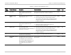
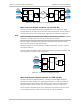
Local FCD-E1LC
Processor
Main
Link
Remote FCD-E1LC
Main
Link
User's
Equipment
Data
Channel
User's
Equipment
Sub
Link
User's
Equipment
Data
Channel
User's
Equipment
Sub
Link
Transmission
Plant
Processor
Figure
6-2. Main Link Remote Analog Loopback
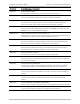
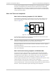
Main Link Local Digital Loopback (LP LOC DIG ML)
This main link local digital loopback is performed by connecting the E1 digital
transmit signal of the main link to the input of the receive path, without passing
through the main link line interface (LIU). Signal paths are shown in
Figure
6-3.
Before activating this loopback on an FCD-E1LC with Ethernet interface,
disconnect the LAN cable from the rear panel Ethernet interface.
The test signal is provided by the equipment connected to the local user ports:
each one must receive its own transmission.
During the loopback, the local FCD-E1LC sends an unframed “all-ones” signal to
the remote FCD-E1LC.
This test checks the digital circuits of the local FCD-E1LC (processor section), and
the connections to the local user’s equipment.
User's
Equipment
Local FCD-E1LC
Processor
Data
Channel
Main
Link
"1"
User's
Equipment
Sub
Link
Figure
6-3. Main Link Local Digital Loopback
Main Link Remote Digital Loopback (LP REM DIG ML)
The main link remote digital loopback is a locally performed digital loopback
towards the remote equipment. The loopback connects, at the local FCD-E1LC,
the regenerated receive signal to the transmit input of the main link interface
within the framer section of the main link interface, as shown in
Figure
6-4.
The test signal is provided by the user's equipment connected to the user ports
of the remote FCD-E1LC: each one must receive its own transmission.
Note