
Specifications


Appendix A Connection Data Installation and Operation Manual
A-10 Data Channel Connection Data FCD-E1LC Ver. 1.0
FCD-E1LC Side Designation Function User’s Side
11 SCEB External Send Clock (wire B) X
12 SCB Send Clock (wire B) –
13 CTSB CTS (wire B) –
14 SDB Send Data (wire B) T
15 SCA Send Clock (wire A) –
16 RDB Receive Data (wire B) S
17 RCA Receive Clock (wire A) U
18 – Not connected –
19 RTSB RTS (wire B) –
20 RCEA External Receive Clock (wire A) –
21 – Not connected –
22 DSRB DSR (wire B) –
23 RCEB External Receive Clock (wire B) –
24 SCEA External Send Clock (wire A) V
25 – Not connected –
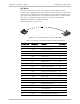
DTE2 Mode
This mode is used to connect to user’s equipment with V.35 DCE interface that
provides the transmit and receive clocks to the FCD-E1LC data channel.
The V.35 cable coming from the user’s equipment is connected to the FCD-E1LC
CHANNEL connector through an adapter cable. The adapter cable (see
Figure A-6
)
is terminated in a 25-pin male D-type connector at the FCD-E1LC side, and a
34-pin female connector at the user’s side. A suitable cable, designated
CBL-HS2V3, is available from RAD.
Cable wiring is given in
Table A-8
.
Table A-8. Wiring of V.35 Adapter Cable for DTE2 Mode
FCD-E1LC Side Designation Function User’s Side
1 FG Frame Ground A
2 SDA Send Data (wire A) R
3 RDA Receive Data (wire A) P
4 RTSA RTS (wire A) F
5 CTSA CTS (wire A) –
6 DSRA DSR (wire A) H
7 SG Signal Ground B
8 DCDA DCD (wire A) C