
Specifications


Appendix A Connection Data Installation and Operation Manual
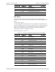
A-16 V.24 Interface Connector FCD-E1LC Ver. 1.0
FCD-E1LC Side Designation Function User’s Side
15 SCA Send Clock (wire A) –
16 RDB Receive Data (wire B) 22
17 RCA Receive Clock (wire A) –
18 – Not connected –
19 RTSB RTS (wire B) 31
20 RCEA External Receive Clock (wire A) 5
21 – Not connected –
22 DSRB DSR (wire B) 24
23 RCEB External Receive Clock (wire B) 23
24 SCEA External Send Clock (wire A) 8
25 – Not connected –
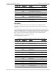
A.4 V.24 Interface Connector
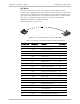
The DHS module with the V.24 interface is supplied with a 25-pin D-type female
connector. The pin allocation in the V.24 interface connector is given in
Figure A-9
identifies the pins of the V.24 connector.
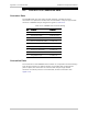
Pin 13 Pin 1
Pin 14
Pin 25
Figure A-9. V.24 Connector, Pin Identification