
Specifications

Appendix C Operating Environment Installation and Operation Manual
C-6 IP Environment FCD-E1LC Ver. 1.0
An IP address is a number selected in accordance with the IP protocol. The only
purpose of an IP address is to permit unambiguous identification of an IP port.
Therefore, each IP port must be assigned a distinct and unique IP address.
The IP protocol does not require the IP port to be related in an unambiguous way
to a physical (communication) port. This has two main implications:
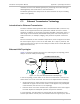
• Since the IP port is actually a connection to an IP network, any number of IP
ports can share a given physical port.
• An IP port may be reached through several physical ports.
By convention, the scope of IP addresses has been extended in two ways:
•
To permit identification of IP networks
•
To permit simultaneous addressing of all the ports connected to a IP network
(this operation is called broadcasting).
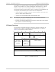
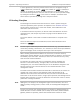
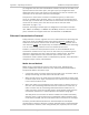
IP Packet Structure
The information exchanged through IP networks is organized in packets. The
structure of an IP packet, as specified by IP protocol Version 4, is shown in
Figure A-2
(the numbers are byte numbers):
0 4 8 12 16 20 24 28 31
IP Version
(4)
IP Header
Length
IP Type of Service
(IP TOS)
Total IP Packet Length
(total number of octets in header + payload)
Fragment Identification
(16 bits)
Flags
(3 bits)
Fragment Offset
(13 bits)
(These fields are used for IP packet fragmentation)
Time to Live
(Range: 0 to 255;
when 0, packet is
discarded)
Number of
Upper-Layer Protocol
Carried in Payload
(IGMP = 2)
(UDP = 17)
IP Header Checksum
Source IP Address
Destination IP Address
Options (when used) Padding (as required)
Payload (maximum bytes: 65535 – “header length”)
.
.
.
Figure C-2. IP Packet Structure
Note