
Specifications

Installation and Operation Manual Appendix C Operating Environment
FCD-E1LC Ver. 1.0 Ethernet Transmission Technology C-11
networks are sent to the default gateway for processing: the router serving as
default gateway then sends them to their destination.
The default gateway must always be in the same IP subnet as the port sending
traffic to the gateway.
C.3 Ethernet Transmission Technology
Introduction to Ethernet Transmission
The basic standard covering Ethernet LANs is IEEE Standard 802.3, which is very
similar to the original Ethernet V2.0 specification (ISO/IEC also have a similar
standard). In addition to the aspects covered by IEEE 802.3 standards, there is a
wide range of LAN standards (the IEEE 802 family) that cover other aspects of
LAN transmission, for example, bridging, with particular emphasis on Ethernet
LANs.
Ethernet standards (in their broadest interpretation) cover the physical and data
link control layers (layers 1 and 2 in the OSI model; IP is a layer 3 protocol). The
data link control layer is split into two sublayers: media access control (MAC) and
logical link control (LLC).
Ethernet LAN Topologies
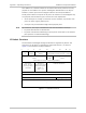
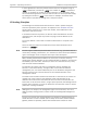
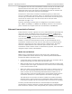
Figure A-3
shows the general structure of a LAN using the star topology, which
today is the most widely used topology.
SD
TX Pair
RX Pair
10/100BaseT Ethernet Hub
Figure C-3. Star (Hub-Based) Ethernet LAN Topology
In the star topology, all the nodes on the LAN are connected to a common unit,
which serves as the hub of the LAN. The hub can be implemented in two ways:
• Simple Ethernet hub, which detects the transmitting node and transparently
distributes its signal to all the other nodes. A hub supports only half-duplex
communication (the same as in a bus topology).
• Ethernet switch: the switch includes more sophisticated circuits that support
both half-duplex and full-duplex operation and prevent collisions.
In a star topology, the LAN cables are usually made of two twisted pairs (one
transmit pair and one receive pair). The standard connector type is RJ-45, and its