
Specifications


Quick Start Guide Installation and Operation Manual
2 Configuration Using a Supervisory Terminal FCD-E1LC Ver. 1.0
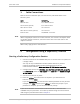
3. Cable Connections
Refer to the site installation plan, and connect the prescribed cables to the
FCD-E1LC ports:
Cable Connect to …
Main link cable E1/T1 MAIN connector
Sub link cable (optional) E1/T1 SUB connector
Data channel 1 cable CH1 connector
Data channel 2 cable (optional) CH2 connector
Ethernet cable 10/100BASE-T connector
When using adapter cables for the data channels, first connect the adapter cable
to the data channel connector, and then connect the user’s data cable to the
adapter connector.
When ready, apply power to the FCD-E1LC.
4. Configuration Using a Supervisory Terminal
Starting a Preliminary Configuration Session
1. Connect a terminal to the CONTROL DCE port on the FCD-E1LC rear panel (use
a straight cable).
You may use any standard ASCII terminal (dumb terminal or personal
computer emulating an ASCII terminal) equipped with an RS-232
communication interface.
Make sure to use VT-100 terminal emulation.
2. Configure the terminal for 19.2 kbps, one start bit, eight data bits, no parity,
and one stop bit. Select the full-duplex mode, echo off, and disable any type
of flow control.
3. Connect the FCD-E1LC to power.
4. Press the <Enter> key several times in sequence: you should see the
FCD-E1LC prompt, FCD>.
If you see PASSWORD> and the FCD-E1LC default password has not yet been
changed, type 1234 and then press <Enter> to obtain the prompt. If your
password is accepted, you will see the FCD-E1LC prompt.
If you cannot establish communication with the FCD-E1LC, reset FCD-E1LC
CONTROL DCE port parameters to the factory defaults using the internal switch
SW2 using the procedure described in Chapter 2.
Note
Note