
Specifications


Installation and Operation Manual Chapter 1 Introduction
FCD-E1LC Ver. 1.0 Functional Description 1-5
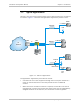
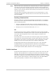
CH.2 LAN connector (optional) – for connection to the 10/100Base-T
Ethernet port.
SUB MAIN
LRLR
CONTROL
RETURN POWER
CH. 2
100 48240 60
//
VAC VDC
SUB MAIN
CH. 1
10 / 100BASE-T
100M
LINK ACT
E1 / T1
E1 / T1
LOOPBACK
DCE
ON
SUB MAIN
LRLR
CONTROL
RETURN POWER
100 48240 60
//
VAC VDC
SUB MAIN
CH. 2
CH. 1
E1 / T1
E1 / T1
LOOPBACK
DCE
ON
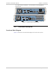
Figure
1-3. Typical FCD-E1LC Rear Panels
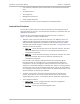
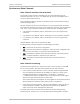
1.4 Functional Description
Functional Block Diagram
Figure
1-4
shows the functional block diagram of the FCD-E1LC system.