
Specifications


Installation and Operation Manual Chapter 1 Introduction
FCD-E1LC Ver. 1.0 Functional Description 1-11
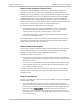
size is automatically selected in accordance with the data channel rate, as listed
in
Table
1-1
.
The values listed in
Table
1-1
are selected in accordance with the limits specified
in the applicable standards.
In addition, when using the DTE2 mode, the FIFO size can also be manually
selected, to enable the user to increase FIFO size when the jitter exceeds the
expected limits.
Table
1-1. FIFO Size vs. Data Channel Rate
Data Channel Rate (kbps) FIFO Size (bits)
64 ±16
128 and 192 ±30
256 through 512 ±52
576 through 1024 ±72
1088 through 1792 ±52
1856 and 1920 ±30
1984 ±16
In addition to payload data, the data channel interfaces handle two additional
types of signals:
• Clock signals. The direction of the clock signals depends on the data channel
timing mode, DCE, DTE1, or DTE2. The timing modes are explained in the
Synchronous Data Channel Timing
section on page
1-14
.
In the DTE2 mode, the clock signal applied to the transmit input is connected
to the clock bus and can be selected as an FCD-E1LC system timing reference.
• Handshaking signals. The handshaking signals are used to control the
exchange of signals with the user’s equipment, in accordance with the
protocol applying to the installed data channel interface. The handshaking is
performed under the control of the management subsystem.
The functions of the handshaking signals are explained on page
1-10
.
Asynchronous Data Channel RS-232/V.24
This interface allows FCD-E1LC to operate opposite external user equipment at bit
rates 1.2, 2.4, 4.8, 9.6, 19.2, or 38.4 kbps. The data rate of the V.24 port can be
selected between 64 kbps and 128 kbps.
Ethernet Interface
The FCD-E1LC can be ordered with a full-feature Ethernet switch with VLAN
support that provides remote bridge services.
The Ethernet switch has a 10/100BaseT interface terminated in a shielded RJ-45
connector for direct connection to LANs.