
Specifications


Installation and Operation Manual Chapter 1 Introduction
FCD-E1LC Ver. 1.0 Timing Considerations 1-19
1.5 Timing Considerations
Main Link Timing Application
Figure
1-5
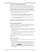
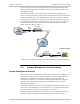
shows a typical application in which FCD-E1LC is operated with the
main link as the timing reference source, and illustrates the flow of timing signals
within the system.
FCD-E1LC
FCD-E1LC
FCD-E1LC
DCE
Timing
DTE1
Timing
User's DTE
E1
Network
User's DTE
User's DTE
Loopback
Timing
ML
Timing
DCE
Timing
ML
Timing
Master Timing
Source
Figure
1-5. Main Link Timing, Flow of Timing Signals in a Typical Application
When using the main link as the timing reference, the data channels must use
DCE timing. However, DTE1 timing can also be used, provided the user’s
equipment connected to the data channels operates with loopback timing, that
is, the user’s equipment must lock its transmit clock to the receive clock provided
by FCD-E1LC.
FIFO buffers are used on the data channels, to absorb small timing variations
(jitter, wander, etc.). FIFO size is automatically selected in accordance with the
data channel rate, as listed in
Table
1-1
.
The main link timing mode is particularly suitable for FCD-E1LC units connected to
an E1 network which has an accurate master timing source (e.g., PTT or national
network), because it enables locking the timing of the equipment connected to
the FCD-E1LC units to the network timing.
Data Channel Timing Application
Figure
1-6
shows a typical application, which uses the data channel operating in
the DTE2 timing mode, as the timing reference source, and illustrates the flow of
timing signals within the system.
In the application shown in
Figure
1-6,
the data equipment located on the
customer’s premises uses the FCD-E1LC link to connect to a data network. Since
data networks include accurate timing sources and do not accept data whose
timing deviates significantly from the network timing, it is necessary to ensure
that the equipment located on the customer’s premises uses the data network
timing.