
Specifications


Chapter 1 Introduction Installation and Operation Manual
1-20 System Management Considerations FCD-E1LC Ver. 1.0
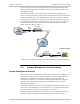
For this purpose, the FCD-E1LC connected to the data network uses the data
channel as its timing source, and therefore its main link timing is locked to the
data network timing.
The FCD-E1LC located on the customer’s premises uses main link timing. As a
result, its system timing is also locked to the data network timing, and the network
timing is transferred to the data equipment located on the customer’s premises.
To optimize jitter performance, the FIFO size of a data channel operating in the
DTE2 mode can be selected manually (±16 bits, ±30 bits, ±52 bits, or ±72 bits).
The manually selected value cannot be less that the automatically selected
values, which are listed in
Table
1-1
.
E1
Network
Customer Premises
User's DTE
FCD-E1LC
ML Timing
Data
Channel
DTE2
Timing
Data
Network
Data
Channel
FCD-E1LC
DCE Timing
Figure
1-6. Data Channel Timing, Flow of Timing Signals in a Typical Application
1.6 System Management Considerations
System Management Method
The FCD-E1LC system is designed for unattended operation. The configuration of
the FCD-E1LC system, that is, a complete collection of operating parameters, is
determined by a database stored in non-volatile memory located in the
management subsystem. The database is automatically loaded upon FCD-E1LC
turn-on, thereby enabling the FCD-E1LC to automatically return to its last
operating configuration.
In addition, FCD-E1LC stores a set of factory-default parameters, which can be
used to start the configuration of a new FCD-E1LC unit; the default parameters
can also be loaded in case the user’s database is corrupted.
FCD-E1LC database management, as well as the other configuration, test and
monitoring activities (equipment status reading, alarm status and history,