
Specifications


Installation and Operation Manual Chapter 2 Installation and Setup
FCD-E1LC Ver. 1.0 Connecting to Power 2-17
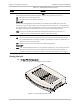
Connecting the CONTROL DCE Port
The front panel CONTROL DCE supervisory port has a 9-pin D-type female
connector with RS-232 interface. The interface (DCE or DTE) is
software-selectable:
• When the interface is configured as DCE, enables direct connection to
terminals and management stations
• When the interface is configured as DTE, it is necessary to use a crossed
adapter cable.
Cables used for the CONTROL DCE port connection must have a frame ground
connection. Use ungrounded cables when connecting a supervisory terminal to a
DC-powered unit with floating ground. Using improper terminal cable may result
in damage to the CONTROL DCE port.
2.8 Connecting to Power
Any interruption of the protective (grounding) conductor (inside or outside the
device) or disconnecting the protective earth terminal can make the device
dangerous. Intentional interruption is prohibited.
Before switching this FCD-E1LC unit on and before connecting any other cable,
FCD-E1LC protective earth terminals must be connected to protective ground.
This connection is made through the DC or AC power cable. The AC power cord
plug should only be inserted in an outlet provided with a protective ground
(earth) contact, whereas when using DC power it is necessary to ground the AD
grounding terminal. The protective action must not be negated by use of an
extension cord (power cable) without a protective conductor (grounding).
Dangerous voltages may be present on the cables connected to the FCD-E1LC:
• Never connect cables to an FCD-E1LC unit if it is not properly installed and
grounded. This means that its power cable must provide a protective ground
(earth) contact before connecting any user or main link cable to the FCD-E1LC.
• Disconnect all the cables connected to the connectors of the FCD-E1LC before
disconnecting the FCD-E1LC power cable.
FCD-E1LC does not have a power on/off switch, and therefore it will start
operating as soon as power is applied. It is recommended to use an external
power on/off switch to control the connection of power to the FCD-E1LC. For
example, the circuit breaker used to protect the supply line to the FCD-E1LC may
also serve as the on/off switch.
AC power should be supplied to the FCD-E1LC through the 5-foot (1.5m)
standard power cable terminated in a standard 3-prong plug.
The connection of the FCD-E1LC to a DC power source is made by means of a
cable terminated in the AC/DC adapter (AD) plug.
Warning
Caution
Caution