
Specifications


Chapter 3 Operation Installation and Operation Manual
3-2 Indicators FCD-E1LC Ver. 1.0
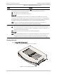
8. If FCD-E1LC successfully passed the power-up self-test, it sends the following
message:
FCD Supervisory Port On Line. Type ‘H’ For Help
Now FCD-E1LC is ready for operation.
If the configuration data stored by FCD-E1LC is corrupted, FCD-E1LC reports that
the self-test has failed or sends the
DATABASE CHECKSUM ERROR
alarm
message.
In this case, you will have to load the default configuration. To do this, either
enter the INIT DB command from the terminal or use the internal switch SW2 as
explained in
Chapter 2
.
3.2 Indicators
Front Panel Indications
For a description of FCD-E1LC front panel indicator functions, see FCD-E1LC Front
Panel on page
2-3
.
As long as the FCD-E1LC is powered, the PWR indicator lights steadily.
During normal operation, the ALM, all the SYNC LOSS, and the TST indicators must
be off.
Any alarm condition causes the ALM indicator to light (for major alarms, it will
flash). Use the supervision terminal to read the alarm messages.
If any of the main link alarm indicators or the TST indicator lights, data transfer is
interrupted.
The TST indicator lights when a test is activated. If the test is activated from the
local FCD-E1LC, see the test type using the supervision terminal (DSP ST CH1,
DSP ST CH2, DSP ST ML or DSP ST SL). You can disconnect a local loop by
means of the CLR LOOP command, as explained in
Appendix D
.
Ethernet Interface Status Indications
If the FCD-E1LC optional Ethernet port is not yet connected to an active LAN, the
LINK indicator is off.
After the connection is made and the auto-negotiation process is successfully
completed:
• The LINK indicator lights steadily
• The ACT indicator lights steadily or flashes at the rate of the traffic flow
through the FCD-E1LC LAN interface
• The 100M indicator indicates the actual operating rate: off for 10 Mbps, on
for 100 Mbps.
Note
Note