
Specifications

Installation and Operation Manual Chapter 5 Configuring FCD-E1LC for a Typical Application
FCD-E1LC Ver. 1.0 Configuration Example 5-5
Enable the CRC-4 function (YES)
Set the idle timeslot code to 7F
Enable transparent reporting of sub link alarms through the main link (RAI
= ENABLE).
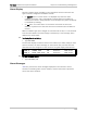
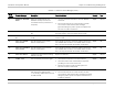
After configuration, you should see the following display:
FRAME CRC-4 SYNC RX_GAIN IDLE_TS_CODE RAI
G732N YES CCITT LONG 3F ENABLE
Configure Sub Link Parameters
Type DEF SL to define the required sub link parameters:
E1 link interface operating mode: SHORT
Framing mode: G.732S
Enable the CRC-4 function (YES)
Set the idle timeslot code to 7F
Enable transparent reporting of sub link alarms through the main link (RAI
= ENABLE)
Use the out-of-service code 3F
Transfer 10 subscriber timeslots and the signaling timeslot (timeslot 16)
through the main link.
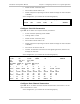
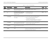
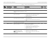
After configuration, you should see the following display:
FRAME CRC-4 SYNC RX_GAIN IDLE_TS_CODE RAI
G732N NO CCITT SHORT 7F ENABLE
CGA OOS_SIG OOS_CODE
NONE N/A 3F
MAP_MODE START_TS TS_TYPE NUM_OF_TS
USER N/A N/A N/A
TS : 1 2 3 4 5 6 7 8
TYPE : DATA DATA NO NO NO NO VOICE VOICE
TS : 9 10 11 12 13 14 15 16
TYPE : VOICE VOICE VOICE VOICE VOIC VOICE VOICE DATA
TS : 17 18 19 20 21 22 23 24
TYPE : VOICE NO NO NO NO NO NO NO
TS : 25 26 27 28 29 30 31
TYPE : NO NO NO NO NO DEDIC NO
Configure Data Channel Parameters
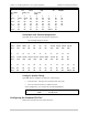
Type DEF CH 1 to define the data channel characteristics and connect it to the
main link timeslots 1 and 2.
After configuration, you should see the following display: