HAL System Design Guide Halogen Software Version 5.
HAL System Design Guide ©Rane Corporation 10802 47th Ave. W., Mukilteo WA 98275-5000 USA TEL 425-355-6000 FAX 425-347-7757 WEB rane.
Table of Contents CHAPTER 1: Welcome to the World of HAL 1 About This Document 1 System Requirements 3 Minimum Requirements for Running Halogen 3 Recommendations for Best Performance 3 Administrative Rights Requirements 4 Using the HAL System Documentation 4 Getting Started 6 CHAPTER 2: Introduction to the HAL System 8 Overview of HAL Devices 11 Available HAL Models 11 HAL Front and Rear Panels 12 Discontinued HAL Models 18 Discontinued HAL Front and Rear Panels 21 Remote Audio D
HAL SYSTEM DESIGN GUIDE HAL1x Expansion Units 58 HAL1 Expansion Unit (Discontinued) 80 Momentary and Latching Toggle Configuration 84 Introduction to the Halogen Software 87 Basic Structure 88 Workspace Layout 89 HAL System Connectivity Required Ports 90 Required Processes 91 CHAPTER 3: Key Audio Design Features 93 About the Distributed Program Bus 93 About Zone Processing 95 About Paging 98 About Control Links 105 Basics of Control Linking 105 Advanced Topics 113 Best Practic
Generating Device Labels 168 Upgrading Halogen Software and HAL Firmware 169 Uninstalling the Halogen Software 170 APPENDIX A: Transitioning from Drag Net 172 Index 175 Glossary 180 v
CHAPTER 1: Welcome to the World of HAL It’s no coincidence that the name of Rane’s new audio system (HAL) matches that of the sentient computer made famous in Arthur C. Clarke’s science fiction book and film titled 2001: A Space Odyssey. In Clarke’s tale, HAL (which stands for Heuristically-programmed ALgorithmic computer) is all-knowing, all-seeing, and (at least initially) a tremendous asset to the astronauts on board the spaceship Discovery.
HAL SYSTEM DESIGN GUIDE work flow to follow when designing and installing a system, and, most importantly, you'll become aware of the key features the HAL System has to offer—functionality that will save you DAYS of work! Yes—days of work! How is that possible? Read on to find out ...
CHAPTER 1: Welcome to the World of HAL System Requirements To use a HAL System, the following items are required: l You must have access to a computer running Microsoft Windows XP (Service Pack 3 or higher), Vista (Service Pack 1 or higher), Windows 7, or Windows 8. The computer must also have an Ethernet port, which you use to connect the computer to the HAL device (either directly or via an Ethernet network via a shielded CAT 5e cable).
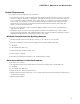
HAL SYSTEM DESIGN GUIDE Administrative Rights Requirements The following table outlines which Halogen tasks require administrative rights and which do not: Requires administrative rights Does not require administrative rights l Installing Halogen l Installing software updates to Halogen l Running and using Halogen l Manually starting or stopping the RaneLink II service l Updating the HAL firmware Using the HAL System Documentation A variety of documentation is available to help you get started
CHAPTER 1: Welcome to the World of HAL example HAL1 configuration and how to set up an AMX controller and touch panel to communicate with a Halogen/HAL Control Server. In addition, an appendix is included with reference information on the HAL external control message protocol and how to use a telnet client to monitor and troubleshoot the operation of a control system at the message protocol level. The guide is designed to be used in conjunction with the files found in the AMX Support Package.
HAL SYSTEM DESIGN GUIDE l Windows XP - C:\Program Files\Rane Corporation\Halogen\Guides\Support Packages\Crestron directory. You can also download the most up-to-date version of this support package from the Rane website (http://rane.com/hal). Stardraw Control Systems Guide This guide, includes an introduction to using external control systems with HAL.
CHAPTER 1: Welcome to the World of HAL l Distributed Program Bus—Talk about a time saver! If you need background music in your installation, simply wire the background music channels to a single block called a Distributed Program Bus and, voila, these channels automatically appear in your zones (as long as you use a Zone Processor or Room Combine Processor to create your zones). See "About the Distributed Program Bus" on page 93 for more information.
CHAPTER 2: Introduction to the HAL System The HAL System includes both hardware and software components. This system introduction provides a broad overview of these components. Hardware Components The primary hardware component in a HAL System is the HAL host device. There is only one HAL device per system. HAL serves as the system's brain to which you connect other slave devices such as analog audio equipment, Remote Audio Devices (RADs), Digital Remotes (DRs), Expansion Units (EXPs), and more.
CHAPTER 2: Introduction to the HAL System 9
HAL SYSTEM DESIGN GUIDE Software Component Included in the HAL System is a software application, called Halogen, that you use to configure and manage the entire system. Halogen contains two primary graphical workspaces, the Hardware Workspace and the Processing Workspace, in which you simply drag and drop hardware components and processing blocks to set up the audio system you want. You can work in online mode (connected to HAL) or offline mode (not connected to HAL or any other hardware).
CHAPTER 2: Introduction to the HAL System Overview of HAL Devices The HAL host device (which is referred to as HAL throughout this guide) is the brain that controls the entire HAL System. It can connect to a variety of other hardware (or slave devices) such as analog equipment, RADs, DRs, and EXPs. Inside the HAL hardware is a DSP audio processing engine and a host controller that controls DSP operations and manages control links, presets, and more. There is only one HAL device per system.
HAL SYSTEM DESIGN GUIDE l 4 Logic Inputs l 2 Relay Outputs HAL3s The device connections that are possible on a HAL3s are as follows: l 2 Remote Audio Devices (RADs) l 2 Digital Remotes (DRs)—Can add up to 2 more by plugging them into the RAD ports l 2 Mic/Line-Plus Inputs l 6 Line Outputs l 4 Logic Inputs HAL4 The device connections that are possible on a HAL4 are as follows: l 1 Digital Remote (DR) l 2 Mic/Line-Plus Inputs l 2 Line Outputs HAL Front and Rear Panels This section include
CHAPTER 2: Introduction to the HAL System 1. The Power IEC jack connects to AC line voltage, 100-240 VAC, 50/60 Hz. 2. Fault, Locate, and Power LEDs The Fault LED (red) turns on when something in the hardware goes awry. The first step in troubleshooting the problem is to open the Halogen software and check the status of this HAL device. The Locate LED flashes green when you place this HAL device in Locate Mode (via the Halogen software).
HAL SYSTEM DESIGN GUIDE This Ethernet port contains auto-MDIX functionality, which means that you can use either a standard Ethernet cable or a crossover cable to connect to a computer or Ethernet switch. The autoMDIX functionality takes care of coordinating the proper connection between the devices. NOTE: The Ethernet LAN LED flashes when HAL detects any Ethernet packets on the network. The Link LED indicates if the Ethernet network is connected.
CHAPTER 2: Introduction to the HAL System The Remote Audio Device LEDs on the front panel differ from those on the rear panel. The front panel LEDs provide information about signal activity on each audio channel. See the "Overview of HAL Devices" on page 11 for more details. NOTE: You can use the Remote Audio Device LEDs on the rear panel and on the RAD to troubleshoot connection problems. TIP : 9. Relay Out ports Reed relay ports used to signal another device.
HAL SYSTEM DESIGN GUIDE 1. Mic/Line Input LEDs Provides status information about mic/line analog inputs connected to the HAL. The numbers correspond to the mic/line input ports on the rear panel. These LEDs provide information on the following: l Overload LED (red) – indicates that the mic/line input is experiencing a signal overload l Signal LED (green) – indicates the presence of an audio signal on the mic/line input 2.
CHAPTER 2: Introduction to the HAL System These LEDs provide information on the following: l Overload LED (red) – indicates that the mic/line-plus input is experiencing a signal overload l Signal LED (green) – indicates the presence of an audio signal on the mic/line-plus input 3. Line Output LEDs Provides information about HAL analog outputs. The numbers correspond to the line output ports on the rear panel.
HAL SYSTEM DESIGN GUIDE If lit, indicates that an Expansion Bus device is properly connected to the HAL. If an Expansion Bus device is properly connected to the port and powered on yet the status LED remains dark, there is likely a problem with the connection. 8. Fault, Locate, and Power LEDs The Fault LED (red) turns on when something in the hardware goes awry. The first step in troubleshooting the problem is to open the Halogen software and check the status of this HAL device.
CHAPTER 2: Introduction to the HAL System For more information about the HAL1 FireWire expansion bus and EXP1 expansion unit, see "HAL1 Expansion Unit (Discontinued)" on page 80. The HAL1x expansion bus uses a proprietary protocol running on a gigabit Ethernet physical layer with expansion devices connected in a daisy-chain configuration as before. The new expansion bus supports 512 output channels and 512 input channels with a maximum cable length of 330 feet (100 meters).
HAL SYSTEM DESIGN GUIDE Click on Show Discontinued Devices to add discontinued HAL devices to the list as shown below: If you click on the New menu button, Halogen opens the HAL Model Picker dialog box.
CHAPTER 2: Introduction to the HAL System In Halogen version 5.0.1 and later, you cannot create a new configuration for the unsupported HAL1 device. NOTE: Discontinued HAL Front and Rear Panels This section includes front and rear panel graphics for HAL models no longer in production and descriptions for each major area on the panels.
HAL SYSTEM DESIGN GUIDE 1. The Power IEC jack connects to AC line voltage, 100-240 VAC, 50/60 Hz. 2. Fault, Locate, and Power LEDs The Fault LED (red) turns on when something in the hardware goes awry. The first step in troubleshooting the problem is to open the Halogen software and check the status of this HAL device. The Locate LED flashes green when you place this HAL device in Locate Mode (via the Halogen software).
CHAPTER 2: Introduction to the HAL System Use these ports to connect each RAD to the HAL via a standard shielded CAT 5e (or better) cable. You must use a shielded Ethernet cable for this connection. If you need more RAD connections, you will need to connect an Expansion Unit with RAD ports (such as an EXP1) to your HAL device. You cannot connect a RAD to a DR port. 7. Digital Remote Device LEDs Provides information about the health of the shielded CAT 5e connection between each DR and HAL.
HAL SYSTEM DESIGN GUIDE Use these ports to connect analog line output devices, such as amplifiers or powered speakers. 13. Line-Plus Input ports Use these ports to connect balanced or unbalanced line input devices. When configured in Halogen for balanced, each input is +4 dBu balanced. When configured for unbalanced, each input is -10 dBV unbalanced, with left and right channels summed to a single mono input. Front Panel Description 1.
CHAPTER 2: Introduction to the HAL System l Overload LED (red) – indicates that the line output is experiencing a signal overload l Signal LED (green) – indicates the presence of an audio signal on the line output 4. Digital Remote LEDs Indicates which Digital Remotes are enabled. Each numbered LED corresponds to the Digital Remote port with the same number.
HAL SYSTEM DESIGN GUIDE The Locate LED flashes green when you place this HAL device in Locate Mode (via the Halogen software). The purpose of this Locate functionality is for verification, when working in the software, of the physical device you are configuring or viewing. The Power LED lights when the HAL hardware is powered on.
CHAPTER 2: Introduction to the HAL System RAD Grounding Careful grounding of RADs is important for optimum performance. Except for the DR4, all RADs and DRs are powered from the +24 VDC & Ground twisted pair located within the shielded CAT 5e (or better) cable connecting them to the HAL system of multiprocessors. The exposed metal of all RADs and DRs is connected to the ground conductor inside the cable and to the cable shield when properly terminated.
HAL SYSTEM DESIGN GUIDE 6. Comm LED: displays a solid green when the RAD detects two things—the communication pair of wires and that communication is established between the HAL and RAD. The light displays solid red if the RAD cannot communicate with the HAL. This is likely due to a problem with the communications pair of wires. 7. Audio Rx LED: displays solid green when the RAD detects that the pair of wires for receiving audio is functioning properly, regardless of the RAD model.
CHAPTER 2: Introduction to the HAL System As it is poor design to plug two microphones into a single microphone input, we do not recommend this practice. WARNING! RADs are hot-swappable. In other words, you can replace a RAD without having to power down the system. The HAL automatically detects the new RAD and configures it using the configuration data stored in the HAL. If the configured RAD and the physical RAD do not match, the HAL front panel Enabled LEDs for this RAD flash yellow.
HAL SYSTEM DESIGN GUIDE Pager1 RAD Setting up paging in the HAL System is as easy as adding zones to groups (called Scenarios), and then specifying the Scenarios into which each paging station can page into. The paging hardware (the Pager1 RAD) then displays the Scenario options available at that station. The user selects the desired Scenario, waits for the Ready green light indicating that all zones in that Scenario are ready to hear a message, presses the talk button, and speaks into the microphone.
CHAPTER 2: Introduction to the HAL System AM1 and AM2 RADs The Automixer 1 (AM1) is a mixer that expands the available microphone channels as well as line inputs, making it easy for an inexperienced operator to quickly set up and manage the audio for a small multimedia presentation involving up to four participants using wired or wireless microphones as well as several additional program sources (such as a laptop computer or a DVD player).
HAL SYSTEM DESIGN GUIDE For more details, see the manuals that accompany the AM1 and AM2. More information on these RADs is also available in the Halogen Help System. RAD27 USB Audio The RAD27 provides a USB audio interface to the HAL system capable of simultaneous stereo playback and recording. Since the RAD27 uses native operating system drivers, no driver installation is required on either Windows operating system or Apple OS X.
CHAPTER 2: Introduction to the HAL System OS X Playback and Recording: Any program that plays in stereo or mono will play to the RAD27, such as iTunes, QuickTime, Keynote, or a website in Safari such as Skype. Apple's GarageBand works well as a recording program. You can simultaneously playback and record with two programs open. For instance, you can play from iTunes into the HAL system and record from the HAL system into GarageBand.
HAL SYSTEM DESIGN GUIDE Select the Rane RAD27 device and click the Set Default button. Now switch to the Recording tab: Select the Rane RAD27 device and click the Set Default button. With Windows XP and Vista, any audio applications currently running will continue to use the previously selected default device. Restart the application to make it use the RAD27 for recording or playback. Windows 7 automatically switches a running application to the newly selected RAD27 default device.
CHAPTER 2: Introduction to the HAL System Remember that Windows likes to play different bleeps and bloops when updates install, devices are plugged in and unplugged, or other operating system events happen. If you do not want these sounds played into your RAD27, turn off Windows system sounds. You can set this by navigating the following path opening the Sound control panel dialog before.
HAL SYSTEM DESIGN GUIDE sionally. You can think of the RADX as an extension cord. You simply roll the cart (if that's what you're using) into the room and connect the RAD on the cart to the RADX in the wall. The port to which the RADX is connected MUST be configured for a specific kind of RAD – and you can only plug in that type of RAD. In other words, you'll need a RADX for each type of RAD you plan to use as a portable device (in each specific location).
CHAPTER 2: Introduction to the HAL System Digital Remote Devices The Halogen software gives you microscopic control over almost every aspect of your audio system. This detailed control is great for the system designer, but not so great for end users who simply want to turn up the volume.
HAL SYSTEM DESIGN GUIDE DR Grounding Careful grounding of DRs is important for optimum performance. Except for the DR4, all RADs and DRs are powered from the +24 VDC & Ground twisted pair located within the shielded CAT 5e (or better) cable connecting them to the HAL system of multiprocessors. The exposed metal of all RADs and DRs is connected to the ground conductor inside the cable and to the cable shield when properly terminated.
CHAPTER 2: Introduction to the HAL System NOTE: A DR1 requires a one-gang standard switchbox for installation into a wall. DR2 A DR2 works well for selecting sources, presets, and room configurations. You can configure a DR2 to behave in one of two ways: l Single Selector: The control acts as a selector switch that can select only one item on the display screen. For example, the display screen might show a list of background music channels.
HAL SYSTEM DESIGN GUIDE NOTE: A DR2 requires a two-gang standard switchbox for installation into a wall. DR3 The DR3 is extremely flexible, as it can control both selection and volume. You can think of the DR3 as two different remotes—a selector and a level. One knob makes a selection, the other knob changes the volume. You can configure a DR3 in one of three ways: l Single Level & Selector: Control a level and selection from the same remote.
CHAPTER 2: Introduction to the HAL System NOTE: A DR3 requires a two-gang standard switchbox for installation into a wall. DR4 The DR4 provides a variety of inputs and outputs: 8 Logic Inputs, 8 Logic Outputs, 8 Analog Control Inputs, and 6 IR Remote Inputs. Logic Inputs These inputs on the DR4 are similar to the Logic In ports on a HAL.
HAL SYSTEM DESIGN GUIDE l Selector: In this option, you can configure one or more Logic In ports to control the state of a corresponding selector control in the Control palette of the Processing Workspace. You can connect a physical device to any or all of the Logic In ports and configure the ports in Halogen so that they make the desired selection according to the state of the physical device.
CHAPTER 2: Introduction to the HAL System The following table shows how changing the physical switch position affects the Logic In ports and the corresponding Selector control: Logic In Port Switch Position Selector Control 4 3 2 1 1 High High High Low Selection 1 2 High High Low High Selection 2 3 High Low High High Selection 3 4 Low High High High Selection 4 A set of DR4 Logic In ports configured as a one-of selector is not a read-only control because the ports only sense wh
HAL SYSTEM DESIGN GUIDE The other type of physical selector device that you can use with a DR4 Logic In is called a ‘Binary Selector’. This type of device converts a physical control setting to a binary output value. For example, you might have a switch that has a number of selections, say from 1 to 10. This switch has five pins total – four contacts and a common.
CHAPTER 2: Introduction to the HAL System The following table shows how changing the physical switch position affects the Logic In ports and the corresponding Selector control: Logic In Port Switch Position Selector Control 4 3 2 1 1 High High High High Selection 1 2 High High High Low Selection 2 3 High High Low High Selection 3 4 High High Low Low Selection 4 5 High Low High High Selection 5 6 High Low High Low Selection 6 7 High Low Low High Selection 7 8 H
HAL SYSTEM DESIGN GUIDE the corresponding level control will be set to 100%, because it is over the allowed 5 V limit. One way to use a DR4 Analog Control Input port is to connect a physical potentiometer as shown in the diagram below, which shows the Rane VR2 Volume Remote connected to a DR4. By wiring it this way, the Vc wiper provides the control voltage to the DR4.
CHAPTER 2: Introduction to the HAL System You should use only linear "B" taper potentiometers with the DR4 Analog Control inputs because the corresponding Level control is ratio-metric (that is ranges from 0 – 100% in a linear manner). The HAL system applies any necessary taper to level controls that participate in a link. For example all Level controls that affect audio gain in the HAL system have an audio taper applied.
HAL SYSTEM DESIGN GUIDE Logic Out ports are used to signal another device. A common implementation is to link a Logic Out port to a Toggle control in Halogen so that an end user can change its value from a DR remote, for example. Also, the Halogen software contains a checkbox for each Logic Out port, the value of which you can include in a preset or link to another control, making it possible to use a preset or control to turn the Logic Out port high (toggle unchecked) or low (toggle checked). 6.
CHAPTER 2: Introduction to the HAL System Provides information about the health of the shielded CAT 5e connection between the DR4 and HAL or EXP1. The Comm LED (on the top row) lights solidly if the DR's data communications pair is working properly. The Power LED (on the bottom row) lights solidly if a HAL or EXP1 is supplying adequate power to the DR port. 5.
HAL SYSTEM DESIGN GUIDE The DR5 provides eight LED output ports that are coupled to the state of the corresponding DR5 switch input controls. You can connect an LED to each port to have a visual indicator of the DR5 operations.
CHAPTER 2: Introduction to the HAL System A DR5 is designed to fit in a standard US two-gang electrical box. Alternatively, you can mount it near a room combine switch panel. NOTE: DR6 The DR6 is a fully customizable touch-screen remote for the HAL system. It supports multiple pages or tabs and any set of levels, toggles, selectors and/or commands. Using the Control Page Designer, you can drag, drop and resize controls any way that’s desired.
HAL SYSTEM DESIGN GUIDE Connection Diagram The DR6 uses a Remote Power Injector (RPI) that connects between a DR port and the DR6 device.
CHAPTER 2: Introduction to the HAL System DR6 Wall Plate The DR6 includes a wall plate that lets you mount the device in a variety of ways: The assembled rear view showing the CAT 5e cable connection to the RPI: 53
HAL SYSTEM DESIGN GUIDE Remote Power Injector (RPI) 54
HAL SYSTEM DESIGN GUIDE Infrared Remote Devices Wouldn't it be great if the HAL system could sense when movable walls change position and automatically reconfigure the Room Combine block to reflect those changes? This is exactly what Infrared Remotes bring to the party. An Infrared (IR) Remote consists of two parts, an IR transmitter that continuously sends an invisible beam of light and an IR receiver that receives that beam.
CHAPTER 2: Introduction to the HAL System When wired correctly, green indicators on the IR2R and IR2S are always lit. Only when the door is open and the IR2R is receiving infrared from the sender does the IR2R’s amber indicator light. The HAL does not check the IR2 wiring for errors. The IR2R’s green indicator flashes when the output is short-circuited. The amber indicator flashes when the signal is marginal, as for a dirty sensor, or if it’s too far away. The IR2 will operate with up to 5 feet (1.
HAL SYSTEM DESIGN GUIDE Expansion Units This section provides an overview of available HAL Expansion Units. The original HAL1 has been discontinued and is now a legacy system that includes a FireWire Expansion Bus and supports a single expansion unit type, the EXP1. Halogen version 3.0.0 introduced a new expansion bus, the HAL1x host, and a variety of new Expansion Units that you can connect to the bus. This section explains both the old and the new expansion systems and the available expansion units.
CHAPTER 2: Introduction to the HAL System HAL1x Expansion Units A single HAL device contains a fixed number of inputs, outputs, RAD ports, DR ports, Logic ports and DSP processing. Expansion devices allow you to expand these resources to fit your application. The expansion bus supports connection of up to 32 expansion devices and has a channel capacity of 512x512 channels. Available expansion devices are as follows: l EXP1x adds eight RAD ports to a HAL1x via the Expansion Bus.
HAL SYSTEM DESIGN GUIDE any given path through the HAL1x, EXPs, RADs, the DSPs and converters. To extend farther than 100 meters, the HAL1x expansion bus is compatible with unmanaged Gigabit Ethernet Media Converters where multi-mode optical fiber allows a maximum distance of 1 km (0.6 miles) and single-mode allows 12 km (7.5 miles) between each EXP device.
CHAPTER 2: Introduction to the HAL System In addition to connecting the physical Expansion Unit hardware to your HAL device, you must also add the Expansion Unit to your HAL configuration. You can connect a maximum of thirty-two Expansion Units to a HAL1x device using a daisy-chain configuration. NOTE: EXP1x Device The EXP1x is a RAD and DR Expansion Unit for the HAL1x expansion bus. It adds 8 RAD ports to your HAL System (providing a maximum of 16 additional input and 16 additional output channels).
HAL SYSTEM DESIGN GUIDE power to the RADs while HAL provides a conduit of control. As soon as the EXP1x is connected, its RAD ports become visible and available for configuration from within the Halogen software. As with all the HAL1x Expansion Units, the EXP1x connects to HAL via a shielded CAT 5e with a cable length maximum of 100 meters (300 feet). If you need more RAD ports than are available on the HAL device, adding an EXP1x is the solution.
CHAPTER 2: Introduction to the HAL System The Remote Audio Device status indicators on the front panel differ from those on the rear panel. The front panel LEDs provide information about signal activity on each audio channel. See the Front Panel description for more details. NOTE: 4. Expansion Bus Jacks and Link LED Use one of these jacks to connect the EXP1x to the HAL1x, using a shielded CAT 5e (or better) cable.
HAL SYSTEM DESIGN GUIDE The Locate LED, which flashes when toggled from within the Halogen software, helps identify a specific EXP — useful if you have more than one EXP installed. The Power LED lights when adequate power is applied to the unit.
CHAPTER 2: Introduction to the HAL System EXP2x Device The EXP2x is a Dante Expansion Unit for the HAL1x expansion bus. Each EXP2x adds 32 Dante Receive and 32 Dante Transmit audio channels to your HAL System at up to 96 kHz sample rates. The EXP2x provides automatic sample rate conversion for easy integration to the 48 kHz world of HAL audio with a Dante network at 44.1, 48, 88.2, or 96 kHz.
HAL SYSTEM DESIGN GUIDE card. All HAL hardware device firmware is stored in the HAL device. See the Help entry “Understanding the Role of Firmware in the HAL System.” What Ethernet switch can I use for my Dante network? Answers to this and many other Dante questions are found here <<< this word ‘here’ is a link (https://www.audinate.com/resources/networks-switches). The Cisco 300 Series Ethernet switches are available in many varieties, such as the 10-port, SG300-10.
CHAPTER 2: Introduction to the HAL System You can also use the Dante Controller Identify function to turn on the EXP2x Locate LED. Because Dante Controller does not provide a way to turn Locate off, the EXP2x includes a 5 minute timeout, which automatically turns off the Locate LED after the Identify function has turned it on. TIP : 3. Expansion Bus Jacks and Link LED Use one of these jacks to connect the EXP2x to the HAL, using a shielded CAT 5e (or better) cable.
HAL SYSTEM DESIGN GUIDE 1. Dante Rx and Tx Audio Channel Signal LEDs When this green LED is on, it indicates audio signal is present on the Dante audio channel. 2. Dante Rx Audio Channel Active LEDs Indicate the state of each Dante Rx (received) audio channel: Off: The channel is not subscribing to any flows on the Dante network. On (solid): Indicates that the channel has successfully subscribed to a Dante Flow.
CHAPTER 2: Introduction to the HAL System The Locate LED, which flashes when toggled from within the Halogen software, helps identify a specific EXP — useful if you have more than one EXP installed. The Power LED lights when adequate power is applied to the unit. You can also use the Dante Controller Identify function to turn on the EXP2x Locate LED.
HAL SYSTEM DESIGN GUIDE EXP3x Device The EXP3x is an 8-channel analog output & DSP Expansion Unit for the HAL1x expansion bus. It adds full support for eight zones of Distributed Background Music and Paging, including 2 RAD ports, 6 DR ports and all of the required Digital Signal Processing. The EXP3x provides power to the RADs and DRs while HAL provides a conduit of control.
CHAPTER 2: Introduction to the HAL System This block is identical in function and use to the Compressor in the HAL, excluding the side-chain input. NOTE: l 5-Band Parametric EQ block with High-cut and Low-cut filters. This block is identical in function and use to the Parametric filter block in the HAL except the number of bell filters is fixed at 5. NOTE: l Line Output with Level and Meters. NOTE: This block is identical in function and use to the analog Line Output in the HAL1x.
HAL SYSTEM DESIGN GUIDE When using an EXP3x in a Room Combine configuration, it is typical to provide a DR3 remote in each base room for Level and Source selection. If eight base rooms each require a DR3 device, you can use the 6 DR and 2 RAD ports on the EXP3x for connecting the required eight DR3 devices. Note that you would link to the Level and Selector in each HAL1x Room Processor block and not to controls in the EXP3x.
CHAPTER 2: Introduction to the HAL System l Toggle: The Toggle configuration allows the state of a toggle control in the Control palette of the Processing Workspace to control the state of the Logic Out port. When the toggle control is unchecked, HAL sets the corresponding EXP3x Logic Out port to logic high (5 V) and when the toggle is checked, it sets the port to logic low (0 V). See the EXP3x data sheet for more details on electrical specifications for the EXP3x Logic Out ports.
HAL SYSTEM DESIGN GUIDE Provides information about the health of the shielded CAT 5e connection between each DR and EXP. The numbers correspond to the DR ports near the center of the rear panel. The Comm LED (on the top row) lights solidly if the DR's data communications pair is working properly. The Power LED (on the bottom row) lights solidly if the EXP is supplying adequate power to the DR port. 7.
CHAPTER 2: Introduction to the HAL System 1. Line Output LEDs Provide information about EXP3x analog outputs. The numbers correspond to the line output ports on the rear panel. These LEDs provide information on the following: l Overload LED (red) – indicates that the line output is experiencing a signal overload l Signal LED (green) – indicates the presence of an audio signal on the line output 2. Remote Audio Devices LEDs Provide information about the RAD audio channels.
HAL SYSTEM DESIGN GUIDE EXP5x Device The EXP5x is an Expansion Unit available for the HAL expansion bus. It provides twelve universal analog inputs. Each input supports Balanced Line, Line-Plus, Dynamic Mic or Condenser Mic. The EXP5x also provides four DR ports for Source Selection, Level Control or Toggle/Command functions. In addition, the EXP5x provides power to the DRs while HAL provides a conduit of control.
CHAPTER 2: Introduction to the HAL System The Locate LED, which flashes when toggled from within the Halogen software, helps identify a specific EXP — useful if you have more than one EXP installed. The Power LED lights when adequate power is applied to the unit. 3. Expansion Bus Jacks and Link LED Use one of these jacks to connect the EXP5x to the HAL, using a shielded CAT 5e (or better) cable. Use the other jack to connect the EXP5x to another Expansion Unit, thus forming a daisy chain.
HAL SYSTEM DESIGN GUIDE 3. Expansion Bus LED If lit, indicates that the Expansion Unit is properly connected to the HAL. If Expansion Units are properly connected to one another and to the HAL port yet this status LED remains dark, there is likely a problem with the connection between the HAL or last Expansions Unit in the chain where this LED is lit and the first Expansion Unit in the chain where this LED remains dark. 4.
CHAPTER 2: Introduction to the HAL System EXP7x Device The EXP7x is an 8-channel AEC DSP Expansion Unit for the HAL1x expansion bus. The device consists of eight, full-featured AEC blocks that include level control, Ambient Noise Reduction (ANR), AGC and 5-Band Parametric EQ. Each connected EXP7x device provides eight full-featured, high-performance AEC blocks. Blocks appear in the DSP TAB under the Conferencing heading.
HAL SYSTEM DESIGN GUIDE Use one of these jacks to connect the EXP5x to the HAL, using a shielded CAT 5e (or better) cable. Use the other jack to connect the EXP5x to another Expansion Unit, thus forming a daisy chain. The Link LED lights when the HAL is communicating with the EXP5x. Front Panel 1. AEC Configuration Blocks These LEDs indicate the number of Acoustic Echo Cancellation (AEC) DSP blocks currently configured for the EXP7x. When lit, that block is included in the current Halogen configuration.
CHAPTER 2: Introduction to the HAL System HAL1 Expansion Unit (Discontinued) A single HAL1 device contains a fixed number of inputs, outputs, RAD ports, and so on. If you purchased a HAL1 but you need more than four RAD ports, you can attach the EXP1 Expansion Unit to your HAL1 and suddenly have eight more RAD ports in your system. Remember that you can also connect DRs to RAD ports, so you could use the EXP1 to expand your DR connections as well.
HAL SYSTEM DESIGN GUIDE In addition to connecting the physical Expansion Unit hardware to your HAL device, you must also add the Expansion Unit to your HAL configuration. NOTE: You can connect a maximum of four EXP1 Expansion Units to a HAL1 device. EXP1 Device (Discontinued) The EXP1 is an Expansion Unit available for the legacy HAL1 expansion bus. It adds 8 RAD ports to your HAL System (providing a maximum of 16 additional input and 16 additional output channels.
CHAPTER 2: Introduction to the HAL System power to the RADs while HAL provides a conduit of control. As soon as the EXP1 is connected, its RAD ports become visible and available for configuration from within the Halogen software. The EXP1 connects to HAL1 via a FireWire1 cable, which has a maximum length of 15 feet. If you need more RAD ports than are available on the HAL1 device, adding an EXP1 is the solution.
HAL SYSTEM DESIGN GUIDE Use one of these jacks to connect the EXP1 to the HAL, using a FireWire1 cable. Use the other jack to connect the EXP1 to another Expansion Unit, thus forming a daisy chain. The Link LED lights when communication is occurring between the EXP1 and HAL or between the EXP1 and another expansion unit in the daisy chain. 5. Remote Audio Device Ports Use these ports to connect each RAD to the EXP1 via a standard shielded CAT 5e cable.
CHAPTER 2: Introduction to the HAL System Momentary and Latching Toggle Configuration All of the Logic inputs in the HAL system, including those in the HAL hosts, the DR4, and the DR5, allow you to configure each input port as a toggle and to specify them as either Momentary or Latching. What does this mean? When you have configured a Logic In port as a toggle, Halogen creates a corresponding toggle control in the Control palette of the Processing Workspace.
HAL SYSTEM DESIGN GUIDE Once you have configured the DR5 in the Hardware Workspace, Toggle controls appear in the HW Control palette of the Processing workspace. You can then link each control to any other Toggle control in your system. The following diagram shows the Control palette and a corresponding Toggle control for the DR5 and how to link it to a wall toggle control in a Room Combine block.
CHAPTER 2: Introduction to the HAL System What is Latching and how do I use it? The other way to configure a Logic In port is Latching. You use this setting when you wish to connect a two state device to the Logic In port, where the device remains in one state or the other for the duration of the condition you are signaling to HAL.
HAL SYSTEM DESIGN GUIDE What are other differences between Momentary and Latching settings for a Logic In toggle? Momentary and Latching are also different in the following ways: l When a port is set to Latching, the corresponding toggle control is read-only. This means that when the toggle control is a participant in a link, it is the only control that sets the value for all participants in the link. Also, there can be only one read-only participant in a link.
CHAPTER 2: Introduction to the HAL System Basic Structure The Halogen software is divided into three main sections: the Application Framework, the Hardware Workspace, and the Processing Workspace. Following is an explanation of the purpose of each section: l Application Framework: Manage global tasks such as discovering, connecting to, and applying configurations to HAL devices. Manage and configure the software application itself.
HAL SYSTEM DESIGN GUIDE l Processing Workspace: Wire together the audio processing components of your system, adding and configuring processing blocks such as equalizers, matrix mixers, compressors, limiters, and so on. Manage and configure control links, presets, paging, and room combine layouts. Notice that Halogen separates the hardware view from the processing view of your audio system.
CHAPTER 2: Introduction to the HAL System HAL System Connectivity In addition to understanding the details of the HAL System hardware and software components, it is important to also understand how HAL and Halogen communicate. Following is some important information to keep in mind when designing your system, especially if you will be handing it off to someone else for installation.
HAL SYSTEM DESIGN GUIDE Local Port Remote Port Protocol Purpose 68 67 UDP DHCP Client 4996 Any TCP External Control systems 80 (HAL) Any TCP Web Controls web server (PC or HAL) 8880 (PC) Required Processes The following processes are required for working with the HAL System and for establishing a connection between Halogen and HAL. Process Purpose Location Halogen.exe‡ Use to design your entire audio system and connect to your HAL device.
CHAPTER 2: Introduction to the HAL System l To configure a static IP or enable DHCP on a HAL, you should first connect to the HAL via its link-local address. In other words, it is best to configure these addresses prior to connecting the HAL to your network.
CHAPTER 3: Key Audio Design Features This chapter contains detailed information about the HAL System's major audio design features. Included is conceptual background material to help you understand why each feature works as it does and how to best use the feature. About the Distributed Program Bus A common request for many audio systems is the delivery of background music or some other audio source to all (or many) zones.
CHAPTER 3: Key Audio Design Features The following image illustrates the relationship between the Distributed Program Bus and Zone Processor block: When should I use a Distributed Program Bus? To determine if a Distributed Program Bus would be useful in your system, ask yourself this question: Does my system contain one or more audio inputs that are common to two or more of my output zones? If yes, then a Distributed Program Bus may be the right block for you! Remember that, when using the Zone Processor b
HAL SYSTEM DESIGN GUIDE Can I perform pre- or post-processing on Distributed Program Bus audio sources? You can perform pre-processing on the input to the Distributed Program Bus. You can perform post-processing as well, but not from the Distributed Program Bus itself. You configure post-processing from within the Zone Processor or other processing blocks placed after the Zone Processor block.
CHAPTER 3: Key Audio Design Features With the exception of the last item on this list (configuring emergency paging), the HAL System Zone Processor streamlines all of these tasks and minimizes the hands-on configuration needed to get an output zone up and running. At its simplest, all you need to do is drop a Zone Processor block into your system, wire in the zone's local inputs, add optional post-processing, and connect to the appropriate output(s).
HAL SYSTEM DESIGN GUIDE As you can see, the Zone Processor contains three connected processing blocks: a Priority Selector block, a Level block, and a Paging Zone block. Each of these blocks serves an important function for the zone, as detailed below. The order in which the blocks are connected is also important, with the placement of the Level block before the Paging Zone ensuring that a page is audible regardless of the volume setting for the zone's output.
CHAPTER 3: Key Audio Design Features properties, simply double-click it or hover over its title bar and click the properties icon that appears in the upper right corner. As with the other internal Zone Processor blocks, this block is identical to the generic Paging Zone block. When should I include a Zone Processor block in my audio design and how many do I need? When to use a Zone Processor is a simple decision.
HAL SYSTEM DESIGN GUIDE using presets to control zone configurations. Instead, what you do worry about (although you needn't worry as it is so easy to use!) and what you need to configure is which paging stations can page into which zones. Hard to believe? Read on to learn how this powerful paging system works.
CHAPTER 3: Key Audio Design Features Paging stations and paging zones are probably familiar concepts, but you may not have worked with the concept of a paging scenario before—so now is a good time to pay attention! The first rule to absorb is that you ALWAYS page into Scenarios. "You mean I don't page into zones?" No, you don't. Your paging zones are the building blocks for creating Paging Scenarios. A Scenario can contain one zone, all of your zones, or a subset of zones.
HAL SYSTEM DESIGN GUIDE is paging into Scenario A, Paging Station Y tries to page into Scenario B. What should happen? Should Paging Station Y's page go through to Zone 3 but not to Zone 2 (because Paging Station X is currently paging into Zone 2)? Or should the page go through to both zones, overriding the current page into Zone 2? Or should Paging Station Y be prevented from sending the page because of the conflict? Answering these questions is the purpose of the Scenario Priority.
CHAPTER 3: Key Audio Design Features Paging State Definition Result Busy At least one of the paging zones in the selected Scenario is currently being paged into through a Scenario of equal or higher priority. The user cannot page into the Scenario until the status indicator changes to Ready (or Caution). Caution At least one of the paging zones in the selected Scenario is currently being paged into through a Scenario with a lower priority.
HAL SYSTEM DESIGN GUIDE the emergency block and end user level controls for the zone will have no impact on the volume of the emergency page. For a specific zone, place its Emergency Paging Zone block directly before the zone's output block. If necessary to protect your equipment, however, you may want to include Compressor or Limiter blocks between the Emergency Paging Zone and the output blocks.
CHAPTER 3: Key Audio Design Features if you have all of your zones configured first, although you can edit your Scenarios (adding or removing zones) as you go. What are some best practices to follow or issues to consider when configuring and working with the HAL paging system? For a specific zone, place its Emergency Paging Zone block directly before the zone's output block.
HAL SYSTEM DESIGN GUIDE About Control Links This section contains the background information you'll need for working effectively with HAL System control links. What you need to know, however, depends on what you're trying to do: l Are you creating links that connect only one control to another, with each control participating in only one link? You'll find everything you need in Basics of Control Linking. Reviewing the Best Practices section is also a good idea, but you can skip Advanced Topics.
CHAPTER 3: Key Audio Design Features What types of control links are there? The HAL System includes four types of control links (Level, Selector, Toggle, and Command). All controls participating in a control link must be the same type. The four control types are described below: Level controls Level controls, which are generally associated with volume, have a continuous series of states that are represented by a slider.
HAL SYSTEM DESIGN GUIDE item from a list. Uses for a Selector control might include selecting a music channel, a preset, a room combination, and so on. You would typically link a Selector control to a DR capable of displaying a list (for example, a DR2 and a DR3). HAL processing blocks that contain linkable Selector controls are DR blocks (only for DRs that are capable of displaying a list, such as a DR2 and DR3) and Selector blocks (Selector, Selector with Priority, Router).
CHAPTER 3: Key Audio Design Features Command controls A Command control has no state. It simply allows you to initiate an action. Unlike a Toggle, you cannot undo a Command. The most common usage of Command controls is to assert a preset. Command Control Example: Suppose you have configured several presets containing different audio configurations for the same room. You want to give the end user the ability to assert the appropriate preset depending on the current audio needs of the room.
HAL SYSTEM DESIGN GUIDE Let's say you plan to use a DR1 in the lobby of a restaurant to control the volume of the music playing in the dining room. Sometimes the music plays in the lobby as well and, in those instances, you want the DR1 to control the volume in both the dining room and the lobby.
CHAPTER 3: Key Audio Design Features The originating control is known as the source and the other control is the target: When you drop the link icon from the first control onto the link icon of the second control, a dialog box appears containing up to three possible actions: l If the two controls are not participants in any other control links, the dialog box contains one option: Create New Link: l If the source control is a participant in any other control links, the dialog box contains an additional o
HAL SYSTEM DESIGN GUIDE l If the target control is a participant in any other control links, the dialog box contains an additional option: Add To Link: In other words, you can select Add To Link to add the source control to a link in which the target control already participates. You can select Create New Link to create a brand new control link between the source and target. Or you can do both. See Creating a Control Link in the Halogen Help System for more details.
CHAPTER 3: Key Audio Design Features Notice that the Enable checkbox control is also linkable. We know this because of the link icon that appears next to the checkbox label. This checkbox is a Toggle control. It can have two states: Enabled (checkbox is selected) and Disabled (checkbox is deselected). You could also have a preset that enables or disables a specific DR control.
HAL SYSTEM DESIGN GUIDE the toggle to be a read-only control—a characteristic that has ramifications for the control links in which it participates: l When a link containing a read-only control is active, only the read-only control is enabled in the Halogen software. For example, if you link a two-position switch (connected via a Logic In port) to a Mute control in your Halogen Processing Map, you will no longer be able to toggle the Mute checkbox. It will be disabled in the software.
CHAPTER 3: Key Audio Design Features What happens if a single item participates in more than one control link? There is no restriction on the number of control links in which a control can participate. However, the control cannot be active in more than one link at a time. For example, a single DR1 Level control could participate in two different control links (Link1 and Link2). But if both Link1 and Link2 are active, the DR1 Level control can be active in only one of the links.
HAL SYSTEM DESIGN GUIDE example, if you plan to be deactivating and re-activating control links, you definitely need to understand the Link Master! To fully explain the Link Master function, let’s begin with a scenario. Suppose that you have two Level controls in your system (LevelA and LevelB). In most situations, these two Level controls work independently, but in a few cases they must track one another. Therefore, you create a control link (Link1) that links LevelA and LevelB.
CHAPTER 3: Key Audio Design Features After activating the link: What happens if LevelB participates in another control link (Link2) which is higher priority than Link1? If Link2 is activated, its control link value and all its participants take on the value of the Link2 Link Master (which could be LevelB). LevelB will not be an active participant in Link1 until Link2 is deactivated. When Link2 is deactivated, assuming Link1 is still active, LevelB will become an active participant in Link1.
HAL SYSTEM DESIGN GUIDE Both Link 1 and Link 2 are active: 117
CHAPTER 3: Key Audio Design Features Link 1 is active, Link 2 is inactive: At this point, you may be wondering several things: How is the Link Master selected? Halogen automatically selects the Link Master when you initially create the control link. l If you are creating your control link by dropping one control onto another, your initial control link target1 becomes the Link Master.
HAL SYSTEM DESIGN GUIDE There are a few situations, however, in which your choices for Link Master are limited or are made for you: l If one of the participants is a read-only control, the read-only control is always the Link Master because its value cannot be changed by software. In this situation, the ability to change the Link Master is disabled. l Dynamic selectors (such as the Selector on DR2s and DR3s) cannot be Link Master because they have no value when they are not active in a control link.
CHAPTER 3: Key Audio Design Features A handy way to view the links in which a control is a participant is the Link References dialog box. From this dialog box, you can also access details about each displayed link. To access a control's Link References dialog box, simply click the control's link icon. Note that if the control is a participant in only one link, there is no Link References dialog box, but only the single Link dialog box.
HAL SYSTEM DESIGN GUIDE About Room Combine Designing the audio for a room combine environment is easy, right? It's no big deal that the system must adapt to changing physical spaces. In fact, it's probably one of your favorite types of systems to design. Or is it? Our guess is that you're shaking your head no while memories of merged automixer nightmares, complex matrices, myriad presets, and math and control-intensive designs swirl through your mind.
CHAPTER 3: Key Audio Design Features You continue this process until you've configured all five rooms. This simple procedure combined with the streamlining provided by the Distributed Program Bus and the HAL Paging System make it possible for you to complete a room combine design with a minimum amount of wiring and time ...
HAL SYSTEM DESIGN GUIDE To the left is an image of a Room Combine Processor block. The block displays the base rooms in your room combine (as well as providing connection points for wiring inputs and outputs, but we'll get to that in a moment). A base room is a room that cannot be subdivided. It can be combined with other base rooms to form new rooms, but it cannot be broken down any further.
CHAPTER 3: Key Audio Design Features The dark blue lines indicate that the wall between Rooms A and B is movable and the long wall separating Room C from Rooms A and B is movable.
HAL SYSTEM DESIGN GUIDE As base rooms and walls are arranged in the Room Combine property dialog, a unique Room Processor is created for each base room combination (For example a room processor could be created for room combination A, B, C, A+B, B+C, and A+B+C). The total number of Room Processors in the configuration is calculated by adding together the Room Processors assigned to each Room Combine block in the configuration.
CHAPTER 3: Key Audio Design Features HAL paging system and automatically shows up in the Paging Manager—as noted by the green Zone rectangle in each room. On the output side, each base room has two outputs: Record Out and Room Out. Just as it says, Record Out is intended for routing output for recording purposes. The Record Out node sends pre-level and pre-page output to its destination—thus avoiding volume changes or page interruptions from being recorded.
HAL SYSTEM DESIGN GUIDE As you can see, the Room Processor contains the blocks (already routed appropriately) that are needed for configuring the room's audio.
CHAPTER 3: Key Audio Design Features section to learn the answers to all these questions. The information in this section makes sense only after absorbing the basics of working with the Room Combine Processor block. If you have not reviewed What are the basics of working with this block? (located above), you should do so before continuing.
HAL SYSTEM DESIGN GUIDE l Or create the link by opening the Room Processor for each room and configuring the link between the Level control and the remote device (we'll use a DR1), as shown in the following image: After creating this link, you do the same in the Room B Room Processor. You now have a DR1 in Room A that controls the volume in Room A and a DR1 in Room B that controls the volume in Room B. So what happens when you combine the two rooms? Well, at this point, nothing.
CHAPTER 3: Key Audio Design Features Paging in a Room Combine Imagine you're the receptionist at a large conference center and you receive an emergency call for a conference attendee named Jonathan Clark. The caller knows that Mr. Clark is currently in Session 3A. You look it up and see that Session 3A is being held in the Flamingo Room.
HAL SYSTEM DESIGN GUIDE And this is how the three paging zones appear in the Paging Manager: Paging into any of these zones will send the page to the appropriate output for the currently-active room configuration. Distributed Program Bus in a Room Combine The Distributed Program Bus behaves in a room combine just as it does in a Zone Processor. Its channels are automatically included in every room's inputs, regardless of the room combination.
CHAPTER 3: Key Audio Design Features The main preset included in each Room Processor cannot be deleted and is initially empty. When you create a link within the Room Processor, it is added to the preset with an activation state of true. (The link is also added to the Baseline, but with an activation state of false.
HAL SYSTEM DESIGN GUIDE Another option for providing control to end users is to link the Selector control associated with the list of possible Room Combinations to a DR2 or DR3: Using the Selector control method, the end user selects which configuration is currently active (instead of selecting which walls are open or closed). If there are more than 20 possible room combinations, you cannot link this Selector control to a DR, as the DR cannot display more than 20 selections.
CHAPTER 3: Key Audio Design Features 6. What is the layout of the rooms in your room combine? Open the Room Combine Processor block and configure the layout of the rooms as well as which walls are movable. 7. Do you need to customize the audio processing in one or more rooms? Open the relevant Room Processors to do so. In reality, you could stop here and have a functioning room combine system.
HAL SYSTEM DESIGN GUIDE About Presets This topic contains the background information you need to work effectively with HAL System presets. In addition to reviewing these conceptual details and best practices, we highly recommend that you review the included preset examples and the detailed descriptions of the various preset tasks you can perform. What is a preset and why would I use one? A preset is basically a snapshot of one or more system blocks with their parameters set to specific values.
CHAPTER 3: Key Audio Design Features using a preset to activate and deactivate the appropriate control links. Remember, however, that you cannot use a preset to change the control link's participant list, its Link Master designation, or its priority. If a block that you add to a preset contains a control that is a participant in a control link, that control link's activation state is automatically saved to the preset.
HAL SYSTEM DESIGN GUIDE The following table lists the parameter values for both the current system and for the preset: Gain parameter Off @ Min parameter Mute parameter Current Working Values -35.2 dB Selected Deselected Lobby Preset -6.5 dB Selected Deselected When you apply the preset, all of the preset's LobbyVolume block parameters become the current working values.
CHAPTER 3: Key Audio Design Features As you can see, the most recently applied preset has the highest priority. So how does that play out for block parameters that exist in multiple presets? To find out, let's follow the life of a single block as multiple presets are applied. We'll use a RAD1 Mic Input block for this example.
HAL SYSTEM DESIGN GUIDE Block Parameters PresetA PresetB PresetC Sensitivity Gain 26 37 26 +24 V Phantom Power Not Checked Checked Checked Level Gain -60 -41 -60 Off @ Min Checked Not Checked Not Checked Mute Not checked Not Checked Checked Now let's look at what happens to each block parameter as a new preset is applied. We'll apply PresetA, then PresetC, and then PresetB. Each table below shows the working values before and after the preset is applied.
CHAPTER 3: Key Audio Design Features Apply PresetA Block Parameters Working Values Before Applying Preset Working Values After Applying PresetA Sensitivity Gain 43 26 +24 V Phantom Power Not Checked Not Checked Level Gain -34.
HAL SYSTEM DESIGN GUIDE Block Parameters Working Values Before Applying Preset Working Values After Applying PresetB Off @ Min Not Checked Not Checked Mute Checked Not Checked In essence, when working with presets, simply remember that the working values of a system block always reflect the values found in the most recently applied preset that contains that block. If no preset has affected a specific block, that block continues to reflect its original (or default) values.
CHAPTER 3: Key Audio Design Features If a preset, regardless of its control type, appears anywhere in the Active Presets list, that preset is active. The working values of the parameters for a specific block reflect the values in the highest priority preset that contains that block. NOTE: To thoroughly understand what happens when you activate and deactivate presets, you need to understand what the Baseline preset is and how it works.
HAL SYSTEM DESIGN GUIDE So what are some other characteristics that distinguish the three different preset types from one another? And how do you decide which type to use? See the About Presets topic in the Halogen Help System to review a table comparing the different preset types.
CHAPTER 3: Key Audio Design Features another active preset containing this DR block existed above the Baseline in the Active Presets list1. Although you could return to the Baseline by asserting it over your activated Toggle and/or Selector presets, causing it to overlay every block in the system, we recommend against this practice.
HAL SYSTEM DESIGN GUIDE that is configured to behave as a Selector. If you created a Toggle preset, you could link it to a Logic In device, or to a Toggle control displayed on a DR2 or DR3. If you created a Command preset, you could link it to a Command control displayed on a DR2 or DR3 or to a Logic In configured as a Command control. For procedural details, see Linking a Preset to a DR or Other Remote Device in the Halogen Help System.
CHAPTER 3: Key Audio Design Features If you decide to use the ScratchPad feature, you will likely control it from within the Halogen software. If, however, you need to expose a control for enabling, disabling, and/or resetting the ScratchPad, you can do so using control links. The ScratchPad's two controls—the Enable/Disable Toggle control and the Reset Command control—can be linked to a DR or some other remote hardware device.
HAL SYSTEM DESIGN GUIDE your Baseline. You can configure your entire system and save it to the Baseline all at once, or you can move from block to block, saving each block to the Baseline as you go. See Customizing the Baseline Preset for procedural details. Name your presets as soon as you create them. This helps alleviate confusion later. Note that all preset names must be unique.
CHAPTER 3: Key Audio Design Features About Control Pages This section contains the background information you need to work effectively with HAL System Control Pages. In addition to reviewing these conceptual details and best practices, we highly recommend that you review in Halogen online help the included Web Controls and DR6 starter configuration examples and the detailed descriptions of the various tasks you can perform.
HAL SYSTEM DESIGN GUIDE system: Command1, Level2, Toggle3, and Selector4. You can use existing external controls that you've created in the External Controls dialog, or you can create new controls in the Control Page Designer dialog. No matter where you create them, once they are present you can link them to other controls in your configuration and add them to one or more control pages.
CHAPTER 3: Key Audio Design Features Halogen then creates a control on the page: Controls that you've placed in the control page layout area represent the controls on the page, but they are not live controls and do not operate if you try to use them. To actually try out a control, you need to preview the page in a web browser or in the DR6 Viewer dialog, depending on which devices you've assigned the page to.
HAL SYSTEM DESIGN GUIDE What other elements can I add to a control page? To allow more functionality, better usability and better appearance of your control pages, Halogen allows you to add additional elements to a page: Page Element Purpose Image Choose .jpg, .png, and .gif files from your PC file system and add them to your control pages.
CHAPTER 3: Key Audio Design Features l Change the page color theme - Halogen supports several built-in themes for control pages that set the colors of all elements on a page and the page background color. l Set element components to custom colors - Many of the controls and other page elements have customizable colors that you can set to any one of a variety of colors.
HAL SYSTEM DESIGN GUIDE How does the end-user change from one control page to another? If you have multiple control pages in your Halogen configuration, you will probably want end-users to be able to change from one page to another. Halogen provides multiple ways to do this: Page Links A page link is a button on a control page that tells the HAL web server or DR6 device to change from the current page to another page configured in the system.
CHAPTER 3: Key Audio Design Features DR6 Auto-Navigation Settings The DR6 device provides built-in auto-navigation features: l a set of navigation tabs l a single button that opens a navigation popup window You can use either one of these options for any DR6 in your system. For more information see (DR6) Device Setup.
HAL SYSTEM DESIGN GUIDE Configure user access settings and page assignments by clicking on the Page Access button Control Page Designer dialog: For more information see Configure Page Access Dialog Box. Advanced Topics Can a control be read-only on a control page? Yes! All of controls include an Enable check box that affects how the control appears and operates on the page. When the box is checked, the control is enabled and fully operational on the control page.
CHAPTER 3: Key Audio Design Features same page or different pages. Can an external control system connect and interact with HAL when control pages are in use? Yes! Because HAL Control Pages uses the External Controls infrastructure, it is possible to use HAL Web control pages, DR6 control pages and other external control systems at the same time, even using the same set of controls.
HAL SYSTEM DESIGN GUIDE Designer dialog. The Label is a property in the dialog that appears. For example: Always test your controls and links they participate in by clicking the Preview Page button in the Control Page Designer dialog and selecting Web: or a DR6 device, depending on your application. Since the same web server runs in both Halogen and in the HAL, you do not need a HAL device to check the initial versions of your web pages.
CHAPTER 3: Key Audio Design Features Add more users and configure page assignments in the Configure Page Access dialog if you want to prevent unauthorized users from accessing HAL control pages.
CHAPTER 4: Designing and Installing Your HAL System Now that you understand the basics of the HAL System (assuming you have read the preceding pages), you're likely anxious to get rolling with this amazing product. Well, hold on for just a few more pages. This section of the Design Guide provides some final bits of information to help you get started. We highly recommend that you review the work flow presented next.
CHAPTER 4: Designing and Installing Your HAL System Step Task Location Choose physical hardware. 3 Decide which physical hardware components you will need to implement your design. Which HAL host do you need: HAL1x, HAL2, HAL3s, or HAL4? Will you be using RADs? If so, which ones and how many do you need? If you need additional RADs, DRs, Zone Processing, or analog inputs or outputs, you may need some Expansion Units.
HAL SYSTEM DESIGN GUIDE Step Task Location Specify processing. 6 Staying in the Processing Workspace, you now move to the DSP palette, where you drag over the processing blocks you want to use in your system. The DSP palette includes blocks for controlling dynamics, filtering, mixing, paging, room combine configuration, and more. Simply drag the blocks you want and drop them anywhere in the workspace area.
CHAPTER 4: Designing and Installing Your HAL System A Few Design and Installation Tips Following are a few simple tips to consider when designing your HAL System and preparing the system for installation: Review the HAL System features before you begin your design! The key features are explained in this guide as well as in the Halogen Help System. TIP : In your system diagrams, use the HAL System CAD drawings provided by Rane. These CAD files are in the .dwg format, a format for AutoCAD.
HAL SYSTEM DESIGN GUIDE 5. The License Agreement appears. After reading the agreement, check the box that indicates you accept the terms, and then click Next. 6. Indicate the location in which Halogen should be installed. By default, Halogen is installed in C:\Program Files\Rane Corporation\Halogen (If running 64-bit Vista or Windows 7 Halogen is installed in the Program Files (x86) directory). Select or deselect the options to create a desktop icon and/or a quick launch icon. Click Next. 7.
CHAPTER 4: Designing and Installing Your HAL System 2. By default, Halogen first shows the Startup Panel, allowing you to create a new configuration for a HAL model of your choice, open an existing configuration file, or connect to a HAL device: . If the application fails to start, verify that all required ports are available and that all required processes are installed and available.
HAL SYSTEM DESIGN GUIDE There are certain changes that, if made on a live HAL device, cause a recompile of HAL's DSP configuration: Wiring changes, addition or deletion from the Processing Map of I/O Processing or DSP Processing blocks, changes to the maximum delay value in the Delay DSP Processing blocks. If a recompile is required, Halogen disconnects from HAL.
CHAPTER 4: Designing and Installing Your HAL System The HAL Configuration Viewer will run and display a window with information about the configuration file: 166
HAL SYSTEM DESIGN GUIDE Creating, Viewing, and Modifying Notes about a HAL System Configuration Halogen provides a simple text editor in which you can capture notes about a specific HAL configuration that may help you remember or help other people understand the details of that particular configuration and its associated devices. These notes are associated with the specific configuration, not with the HAL device itself. You can add notes specific to the HAL device that are stored on the device.
CHAPTER 4: Designing and Installing Your HAL System Generating Device Labels Most RADs (with the exception of the RAD16, AM1, and AM2) contain an area near its top in which you can insert a custom label. We recommend that you use these labels to identify the channel associated with the corresponding jack.
HAL SYSTEM DESIGN GUIDE 6. Click Create. Halogen generates the PDF file and, once it is complete, enables the View button. 7. Click View to open the file. 8. When you are satisfied with the results, print the PDF file. It is best to use 24# paper. 9. Cut out the labels and insert them behind the Lexan window on the appropriate RADs. To help with the alignment of the labels, we recommend that you wait until after inserting the labels before trimming off the excess paper (using an Exacto or box knife).
CHAPTER 4: Designing and Installing Your HAL System If the firmware is newer than the software, a Roll Back Firmware button displays. Instead of rolling back your firmware, however, we strongly recommend downloading the latest version of Halogen, ensuring that you have the latest functionality available to you. NOTE: 2. Click the Update Firmware button to perform the update. As part of the firmware update, HAL also updates the firmware on all peripherals (RADs, DRs, EXPs).
HAL SYSTEM DESIGN GUIDE Here are details: http://blog.rane.
APPENDIX A: Transitioning from Drag Net If you are moving from the Drag Net world to the HAL System world, your transition will be smoother if you read through this topic. Explained below are some of the key differences between the two systems. Understanding Key User Interface Differences As a Drag Net user, you're accustomed to using a Processing Map to design your system.
HAL SYSTEM DESIGN GUIDE As a Drag Net user, were you often tempted to include every relevant block in every preset, even if the preset didn't change a value in the block—just to be sure of every parameter value when recalling the preset? Rest assured that, in the HAL System, this practice is not necessary. You should include in a preset, only those blocks containing a parameter value to be changed by the preset.
APPENDIX A: Transitioning from Drag Net l We save the best for last! Just like with presets, you can now test your control links offline—from within the Halogen software! This is a tremendous benefit for you, the designer. You will know long before your hardware is installed if all your remotes are linked and working correctly. Configuring Remote Device Hardware Configuring your HAL System remote devices is much simpler than in Drag Net.
Index Computer requirements for running Halogen 3 Configuration files Administrative rights requirements 4 AM1 and AM2 RADs 31 Asserting vs.
Controls participating in multiple control links 114 Creating Distributed Program Bus 94 HAL1 expansion bus overview 80 HAL1x expansion bus overview 58 FireWire 80 Firmware, upgrading 169 Device labels, generating 168 Front panel description, Discontinued HAL 21 DHCP, using with HAL 91 Front panel description, HAL 12 Digital RemotesSee DRs Generating device labels 168 Distributed Program Bus Grounding 27, 38 creating 94 HAL Configuration Viewer 164 in a room combine 127 HAL device overview 93
Halogen Maximum connections on HAL3 19 installing and starting 162 Maximum connections on HAL3s 12 introduction 10, 87 Maximum connections on HAL4 12 requirements for running 3 Momentary 84 uninstalling 170 Notes upgrading 169 HALs adding to a Halogen configuration file 167 Overview 1 available models 11 Control Links 105 discontinued models 18 Control Pages 148 Hardware components, introduction 8 Distributed Program Bus 93 Help DRs 37 System 4 Installation installing Halogen 162 HAL1 e
Paging Scenario 99 working with priorities and numbers 100 Paging Station 99 Processes required 91 RAD27 USB Audio 32 RADs Paging status 101 description of hardware 27 Paging System generating labels 168 best practices 104 grounding 27 components 99 overview 26 paging status 101 using as portable devices 35 recommended work flow 103 Paging Zone 99 block in Zone Processor 97 RADs, generating labels 168 RADX 35 Ready status, paging 101 Rear panel description, Discontinued HAL 21 Ports required 9
Routers, using with HAL 91 Paging Zone block 97 Scenario, pagingSee Paging Scenario Priority Selector block 97 Scratch Pad 145 Selector control 106 Selector preset concept 143 Starting Halogen 162 Static IP addresses, using with HAL 91 Status paging 101 Switches, in control links 112 System Overview 1 System requirements 3 Toggle control 84 concept 105 Toggle preset concept 143 Uninstalling Halogen 170 Upgrading Halogen/HAL firmware 169 Workflow for configuring HAL Paging System 103 for creating presets
Glossary A Active Presets list A dynamic list of active presets maintained by the system that changes as presets are asserted, activated, and deactivated. The presets are listed in priority order. When a preset is asserted or activated, it goes to the top of the list and its parameter values overlay the current working values for the corresponding system parameters. When a preset is deactivated it is removed from the list.
HAL SYSTEM DESIGN GUIDE C Command Has no state. A Command control simply allows you to initiate an action. Unlike a Toggle, you cannot undo a Command. The most common usage of Command controls is to assert a preset. Command control Has no state. A Command control simply allows you to initiate an action. Unlike a Toggle, you cannot undo a Command. The most common usage of Command controls is to assert a preset.
Glossary Toggle link maintains the toggle state (on or off). A Command link has no value. D default gateway The default gateway is the device that passes network data from the local network to other networks. DHCP Short for "Dynamic Host Configuration Protocol," a protocol for assigning dynamic IP addresses to devices on a network.
HAL SYSTEM DESIGN GUIDE Level control Generally associated with volume, Level controls have a continuous series of states that are represented by a slider. Link Master The control link participant that dictates the values of the other link participants when the link becomes active. Pertains to Level, Toggle, and Selector control links only. Command control links do not have a Link Master. Link Name A customizable name identifying a particular control link.
Glossary Participants The set of controls participating in a control link. A single control can participate in multiple links but can only be active in one link at a time (determined by link priority). Preset A snapshot of one or more system blocks (with their parameters set to specific values) that you or an end user can apply to the audio system at any given time - typically for a specific event or purpose. Preset Control Type Determines how you and your end users can control the preset.
HAL SYSTEM DESIGN GUIDE Selector Allows the end user to make a selection from a list. Uses for a Selector control might include selecting a music channel, a preset, a room combination, and so on. Selector control Allows the end user to make a selection from a list. Uses for a Selector control might include selecting a music channel, a preset, a room combination, and so on. static IP addresses An IP address that does not change. Static IP addresses must be manually assigned to devices.