
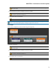
Installation guide


Provides information about the health of the shielded CAT 5e connection between each DR and EXP.
The numbers correspond to the DR ports near the center of the rear panel. The Comm LED (on the top
row) lights solidly if the DR's data communications pair is working properly. The Power LED (on the bot-
tom row) lights solidly if the EXP is supplying adequate power to the DR port.
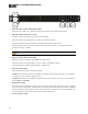
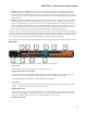
7. Remote Audio Device Ports
Use these ports to connect each RAD to the EXP3x via a shielded CAT 5e (or better)cable. You must use
a shielded Ethernet cable for this connection. There are two RAD ports on an EXP3x device.
8. Remote Audio Device LEDs
Provide status information about the health of the shielded CAT 5e connection between each RAD and
the EXP1. The numbers 1 through 8 correspond to the RAD ports 1 through 8 on the right side of the rear
panel. For example, the LEDs for number 1 provide information about the RAD connected on port 1.
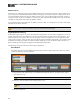
Each LED corresponds with one twisted pair within the shielded CAT 5e cable. If the twisted pair is func-
tioning properly, the LED displays a solid green light when the EXP1 is programmed to expect the RAD
model that is physically plugged in. When all cable pairs are working properly, but HAL is not yet pro-
grammed for the connected RAD model, all four LEDs flash red. Note that flashing red is a good thing:
the cable’s good – just program HAL and you’re done.
l
Audio Rx LED - lights solidly if the EXP1 receive pair is working properly.
l
Audio Tx LED - lights solidly if the EXP1 transmit pair is working properly.
l
Comm LED - lights solidly if the RAD's data communications pair is working properly.
l
Power LED - lights solidly if EXP1 is supplying adequate power to the RAD port.
NOTE: The Remote Audio Device status indicators on the front panel differ from those on the rear
panel. The front panel LEDs provide information about signal activity on each audio channel. See
the Front Panel description for more details.
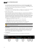
9. Logic Out Ports
Logic Out ports are used to signal another device. A common implementation is to link a Logic Out port
to a Toggle control in Halogen so that an end user can change its value from a DR remote, for example.
Also, the Halogen software contains a checkbox for each Logic Out port, the value of which you can
include in a preset or link to another control, making it possible to use a preset or control to turn the
Logic Out port high (toggle unchecked) or low (toggle checked).
10. Line Output Ports
Use these ports to connect analog line output devices, such as amplifiers or powered speakers.
Front Panel
HAL SYSTEM DESIGN GUIDE
73