
Installation guide

What is Latching and how do I use it?
The other way to configure a Logic In port is Latching. You use this setting when you wish to connect a two state
device to the Logic In port, where the device remains in one state or the other for the duration of the condition
you are signaling to HAL. For example, suppose you have a two position switch that you wish to connect to a
Logic In port in order to allow an end user to mute the audio of an audio output block when the switch is in one
position and to unmute it when the switch is in the other position.
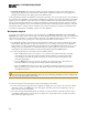
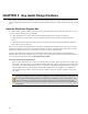
This is what the HAL system does when you configure a Logic In port to be a Toggle and set it to Latching. Set-
ting a physical switch connected to the Logic In port to one position sets the corresponding Toggle control in the
Control palette of the Processing Workspace to ‘checked’, while setting the physical switch to the other position
sets the Toggle control to ‘unchecked’. The diagram below shows this in more detail using a DR4 Logic In port, a
two position physical switch and a HAL Line Output I/O block Mute Toggle control.
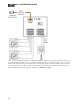
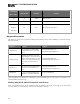
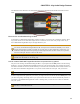
The following diagram shows how to connect a two position switch to the DR4 Switch input port. You should
configure this type of port as Latching in the Hardware Workspace property dialog for the DR4.
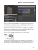
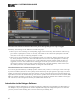
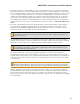
Once you have configured the DR4 in the Hardware Workspace, a Toggle control appears in the Control palette of
the Processing workspace. You can then link this control to any other Toggle control in your system. The fol-
lowing diagram shows the Control palette and the corresponding Toggle control for the DR4 and how to link it to
a Mute toggle control in a HAL1 Line Output block. It also shows a portion the DR4 property dialog from the
Hardware Workspace, with Toggle (29) configured as a Latching Toggle.
CHAPTER 2: Introduction to the HAL System
86