LRS-24 12-slot Link Access Rack with SNMP Version 3.00 Installation and Operation Manual Notice This manual contains information that is proprietary to RAD Data Communications. No part of this publication may be reproduced in any form whatsoever without prior written approval by RAD Data Communications. No representation or warranties for fitness for any purpose other than what is specifically mentioned in this manual is made either by RAD Data Communications or its agents.
Order from: Cutter Networks Ph:727-398-5252/Fax:727-397-9610 www.bestdatasource.
Warranty This RAD product is warranted against defects in material and workmanship for a period of one year from date of shipment. During the warranty period, RAD will, at its option, either repair or replace products which prove to be defective. For warranty service or repair, this product must be returned to a service facility designated by RAD. Buyer shall prepay shipping charges to RAD and RAD shall pay shipping charges to return the product to Buyer.
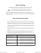
Safety Warnings SEE INSTALLATION INSTRUCTIONS BEFORE CONNECTING TO THE SUPPLY! The exclamation point within a triangle is intended to warn the operator or service personnel of operation and maintenance factors relating to the product and its operating environment which could pose a safety hazard. Always observe standard safety precautions during installation, operation and maintenance of this product.
Additional conditions concerning the safety of connection to telecommunication networks: • The unit must be earthed prior to connection to telecommunication networks. • The signal ground of the SELV circuits is connected at the factory to the protective earth. Interrupting this connection may invalidate the safety of the connection to unprotected telecommunication networks in certain locations where permanent excessive voltages are present on the lines.
Declaration of Conformity Manufacturer’s Name: RAD Data Communications Ltd. Manufacturer’s Address: 12 Hanechoshet St. Tel Aviv 69710 Israel declares that the product: Product Name: LRS-24 Conforms to the following standard(s) or other normative document(s): EMC: Safety: EN 55022 (1994) Limits and methods of measurement of radio disturbance characteristics of information technology equipment.
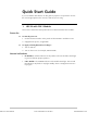
Quick Start Guide If you are familiar with LRS-24, use this guide to prepare it for operation. Choose the section appropriate to the version of LRS-24 you are using. 1. LRS-24 with CM-1 Module This section contains the startup instructions for LRS-24 with the CM-1 module. Power-On ➤ To turn the power on: 1. Set the ON/OFF switches on the panels of the LRSI-PSP** modules to ON. 2. Supply the DC power, as applicable. ➤ To supply external phantom feed voltages: 1. Turn on LRS-24. 2.
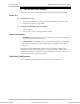
LRS-24 Installation and Operation Manual Quick Start Guide 2. LRS-24 with CM-2 Module This section contains the startup instructions for LRS-24 with the CM-2 module. Power-On ➤ To turn the power on: 1. Set the ON/OFF switches on the panels of the LRSI-PSP** modules to ON. 2. Supply the DC power, as applicable. ➤ To supply external phantom feed voltages: 1. Turn on LRS-24. 2. Turn on the source (for example, LRS-PS-FEED).
Contents Chapter 1. Introduction 1.1 Overview .......................................................................................................... 1-1 General ...................................................................................................................1-1 Versions...................................................................................................................1-3 Application .........................................................................................
Table of Contents Chapter 3. Management via the CM-1 Module 3.1 Introduction ...................................................................................................... 3-1 CM-1 Functions .......................................................................................................3-1 Management Capabilities.........................................................................................3-1 3.2 Hardware Requirements ..............................................................
Table of Contents Appendix A. Connector Wiring Appendix B. LRS-PS-FEED Power Supply Appendix C. SNMP Management Appendix D. CM-2 Management Commands List of Figures 1-1. 1-2. 1-3. 1-4. 1-5. 1-6. 1-7. 1-8. Backbone Data Distribution up to Customer’s Premises............................................. 1-3 Management of Local and Remote Distribution Nodes .............................................. 1-4 LRS-24B 3-D View ....................................................................................
Table of Contents List of Tables 2-1. PS Modules, Front Panel Indicators............................................................................ 2-7 2-2. Module CM-1, Front Panel Components ................................................................... 2-9 2-3. Module CM-1 Jumper Settings................................................................................. 2-11 2-4. Module CM-2, Front Panel...................................................................................... 2-13 2-5.
Chapter 1 Introduction This chapter describes the basic physical and functional features of the LRS-24 modem rack, as well as some typical applications. The following topics are discussed: • Overview • Physical Description • Functional Description • Technical Specifications. 1.1 Overview General Order from: Cutter Networks LRS-24 is a high-density SNMP managed modem chassis. The chassis has 12 slots that accommodate up to 24 modems.
LRS-24 Installation and Operation Manual Chapter 1 Introduction Management/CM-2 functions LRS-24 is managed by a UNIX-based or PC-based SNMP management system via the Central Management card (CM-2). The software is user-friendly, GUI-based and runs under PC/Windows (RADview-PC) or HP OpenView (RADview-HPOV) systems. Configuration and monitoring are also provided via TELNET or ASCII terminal.
LRS-24 Installation and Operation Manual Chapter 1 Introduction Power Supplies LRS-24 operates with single or dual, AC or DC power supplies. Each power supply supports a full LRS-24 hub, including modem cards. Redundant power supply can be replaced during operation, without affecting system performance (hot-swapping). Cards in the LRS-24 chassis are capable of providing remote power feeding for repeaters and remote standalone modems.
LRS-24 Installation and Operation Manual Chapter 1 Introduction Central Management Station PSTN LRS-24 Dial-up Modem ADM or Frame Relay Switch LRS-24 Backbone ADM or Frame Relay Switch PBX LRS-24 PBX Local SNMP Management Station Modem Router Switch LRS-24 Router OP-XL PBX LRS-24 Switch MP2100 Figure 1-2. Management of Local and Remote Distribution Nodes Features LRS-24 is a high-density, fully modular design with front-panel access to all the functions.
LRS-24 Installation and Operation Manual Order from: Cutter Networks Chapter 1 Introduction Remote Management The modem cards in the LRS-24 can be remotely managed by the RADview-HPOV SNMP management system, the PC-based RADview-PC/MDM management system or by a dumb terminal. The same RADview application can manage the LRS-24, modems in the hub and other RAD products.
LRS-24 Installation and Operation Manual Chapter 1 Introduction 1.2 Physical Description Chassis Description There are two different physical versions of LRS-24: LRS-24B and LRS-24F. LRS-24B ANSI UNIT LRS-24B is a modular chassis suitable for installation in standard ANSI racks. It has a height of 200 mm (4U). The chassis has physical slots arranged on the front and back sides: • The front side accepts 4U-high functional modules (the modules that perform the various processing functions).
LRS-24 Installation and Operation Manual Order from: Cutter Networks Chapter 1 Introduction O Rear View Front View Figure 1-3. LRS-24B 3-D View Figure 1-4 shows the LRS-24B enclosure with the Interface Modules, User Modules, Control Logic Module, and Power Supply Module. Physical Description Ph:727-398-5252/Fax:727-397-9610 1-7 www.bestdatasource.
LRS-24 Installation and Operation Manual Chapter 1 Introduction Interface Modules LRS-24B Rear Section User Modules Control Logic Module Power Supply (PS) LRS-24 Front Section Figure 1-4. LRS-24B Enclosure 1-8 Order from: Cutter Networks Physical Description Ph:727-398-5252/Fax:727-397-9610 www.bestdatasource.
LRS-24 Installation and Operation Manual Order from: Cutter Networks Chapter 1 Introduction LRS-24F ETSI UNIT LRS-24F is a modular chassis suitable for installation in standard ETSI racks, having a height of 300 mm (6U). The chassis has physical slots arranged in two rows: • The lower row accepts 4U-high functional modules (the modules that perform the various processing functions).
LRS-24 Installation and Operation Manual Chapter 1 Introduction Interface Modules User Modules CONTROL LOGIC Module Power Supply (PS) Figure 1-6. LRS-24F Enclosure LRS-24 Module Slots The LRS-24F enclosure has a lower section for the functional modules and a top section for interface modules. The LRS-24B enclosure has a front section for the functional modules and a rear section for interface modules. Each section has 15 module slots: • Two slots are reserved for PS modules.
LRS-24 Installation and Operation Manual Chapter 1 Introduction Internal Modules for User Modules LRSI-F2 LRSI-F2 LRSI-F2 LRSI-F2 LRSI-F3 LRSI-F3 LRSI-F3 1 1 Internal Modules for System Slots LINE LINE LINE LINE LINE LINE LINE DCE DCE LRSI-F1-CM2 S T A T I O N 2 2 DCE-1 DCE-1 DCE DCE LRSI-F-PSP / 230 / 115 PHANTOM POWER 150V LRSI-F-PSP / 48 PHANTOM 150V C L K I/O10 I/O11 POWER POWER TD1 TD2 TD1 TD2 RD1 RD2 RD1 RD2 RTS1 RTS2 RTS1 RTS2 DCD1 DCD2 DCD1 DCD2 SYNC LOS S SYNC L
LRS-24 Installation and Operation Manual Chapter 1 Introduction • DC power supply module, PS-LRS/48 – operates on –48 VDC, and provides a maximum total power of 120W. The PS modules are installed in dedicated chassis slots. The chassis has two PS slots, enabling the installation of two PS modules, for redundancy. When both modules are operational, they share the load; in case of failure or loss of input power, the remaining module continues to supply the power alone.
LRS-24 Installation and Operation Manual Chapter 1 Introduction Management Order from: Cutter Networks CM-1 Management Capabilities An ASCII terminal can be used as a supervision terminal to manage the CM-1 module. The supervision terminal is connected to one of the RS-232 asynchronous serial supervisory ports (one port is located on the CM-1 module itself and the second port is located on the interface module serving the CM-1 module).
LRS-24 Installation and Operation Manual Chapter 1 Introduction LRS-24 LRS-24 WAN Supervision Terminal MBE MBE LRS-24 LRS-24 Management Station Figure 1-8. Basic Management Configuration for LRS-24 with CM-2 Modules I/O (User) Modules LRS-24 can be equipped with various types of input/output (I/O) modules to provide the required system functions.
LRS-24 Installation and Operation Manual Chapter 1 Introduction External Clock Interface T1 Mode E1 Mode Type T1 Clock Rate 1.544 MHz Line Interface 100Ω Ω, balanced Line Code Bipolar AMI Receive Level 0 through -10 dB Transmit Level ±3V ±10%, balanced Type E1 Bit Rate 2.048 MHz Line Interface 120Ω, balanced 75Ω, unbalanced Line Code AMI Receive Level 0 through -10 dB Transmit Level ±3V ±10%, balanced ±2.73V ±10%, unbalanced Square Minimum 2.
LRS-24 Installation and Operation Manual Chapter 1 Introduction Hardware Ethernet 10BaseT interface for UTP and STP media Ethernet 10Base2 interface for coaxial media RS-232 asynchronous port, compatible with VT-52, VT-100, FREEDOM-100, FREEDOM-110, and FREEDOM-220 Asynchronous Port Characteristics Data rate: 38.
Chapter 2 Installation and Setup This chapter provides installation and operation instructions for the LRS-24 system, and the basic system configuration of the power supply (PS) and common logic (CM-1 and CM-2) modules.
Chapter 2 Installation and Setup LRS-24 Installation and Operation Manual Figure 2-1. LRS-24F Mechanical Diagram 2-2 Order from: Cutter Networks Introduction Ph:727-398-5252/Fax:727-397-9610 www.bestdatasource.
LRS-24 Installation and Operation Manual Order from: Cutter Networks Chapter 2 Installation and Setup LRS-24B FRONT VIEW WITHOUT MODULES LRS-24B TOP VIEW LRS-24B SIDE VIEW Figure 2-2. LRS-24B Mechanical Diagram Introduction Ph:727-398-5252/Fax:727-397-9610 2-3 www.bestdatasource.
LRS-24 Installation and Operation Manual Chapter 2 Installation and Setup 2.2 Site Requirements and Prerequisites This section describes how to prepare the site for installation of the LRS-24 hub. AC Power Install the LRS-24 chassis with AC power supply modules within 1.5m (5 feet) of an easily accessible, grounded, 100 to 240 VAC outlet. DC Power LRS-24 chassis with DC power supply modules require a –48 VDC power source.
LRS-24 Installation and Operation Manual Caution Chapter 2 Installation and Setup For your safety, always disconnect all the cables connected to an LRS-24 interface module before removing that module from LRS-24. Do not connect cables to an interface module that is not installed in a grounded LRS-24. Module Handling Precautions Caution The LRS-24 modules contain components sensitive to electrostatic discharge (ESD).
LRS-24 Installation and Operation Manual Chapter 2 Installation and Setup 4. Check the packing list against your order to ensure that the supplied modules match your order. If modules have been pre-installed in accordance with your order, check that all modules are in their proper slots and are secure. Report immediately any deviations. 5. Check that all necessary cables have been included. 2.
LRS-24 Installation and Operation Manual Order from: Cutter Networks Chapter 2 Installation and Setup PS-LRS 48VDC PS-LRS/230/115 POWER POWER +5V +5V -5V -5V LRS-24 LRS-24 AC Power Supply Module DC Power Supply Module Figure 2-3. PS Module Panels Table 2-1.
LRS-24 Installation and Operation Manual Chapter 2 Installation and Setup PS Module Installation ➤ To install the first PS module: 1. Make sure that the POWER switches on the two LRSI-PS interface modules are set to OFF. 2. Insert the specified PS module in the PS-A slot, referring to the system installation plan in LRS-24 Module Slots, Chapter 1. 3. Fasten the PS module with the two screws. 4. If an additional redundant module is used, install it in the PS-B slot.
LRS-24 Installation and Operation Manual Order from: Cutter Networks Chapter 2 Installation and Setup POWER TD RD M A N A G E M R E S N T 2 3 2 CM-1 Figure 2-4. Module CM-1 Front Panel Table 2-2.
LRS-24 Installation and Operation Manual Chapter 2 Installation and Setup Internal Jumpers Figure 2-5 shows the location of the user-selectable jumpers located on the CM-1 module. Figure 2-3 lists the jumper settings. The CM-1 module includes additional factory-set jumpers, which must not be moved by the user.
LRS-24 Installation and Operation Manual Chapter 2 Installation and Setup Table 2-3. Module CM-1 Jumper Settings Jumpers Description Values JP4, JP5, JP6, JP9, JP10, Select the station clock interface in the STATION CLK connector of the LRSI-F-CM1 interface module. T1 interface (1544 kHz clock): Set jumper JP5 in the T1-DSU position and jumpers JP9 and JP10 to BAL. Balanced E1 interface (2048 kHz clock): Set jumper JP4 in the E1-BAL position, and jumpers JP9 and JP10 to BAL.
LRS-24 Installation and Operation Manual Chapter 2 Installation and Setup CM-1 Installation Procedure ➤ To install CM-1: • Insert the CM-1 module into the CL slot, and fasten it with the two screws. CM-2 Module This section covers the installation of the CM-2 module in an LRS-24 enclosure. Front Panel A typical front panel for the CM-2 module is shown in Figure 2-6. The functions of the components located on the front panel are listed in Table 2-4.
LRS-24 Installation and Operation Manual Order from: Cutter Networks Chapter 2 Installation and Setup Table 2-4.
LRS-24 Installation and Operation Manual Chapter 2 Installation and Setup Clock Selection E1 E1 T1 75 120 100 E1 E1 T1 75 120 100 E1 75 Unbalanced E1 E1 T1 75 120100 JP2 JP8 JP9 JP3 JP1 JP4 JP5 JP7 JP6 JP2 JP8 JP9 JP3 JP1 JP4 JP5 JP7 JP6 JP2 JP8 JP9 JP3 JP1 JP4 JP5 JP7 JP6 E1 120 Balanced T1 100 Balanced BYPASS PASSWORD JP15 JP16 SCC1 SCC2 JP14 J1 E1 E1 T1 75 120100 JP12 JP2 JP8 JP9 JP3 JP1 JP4 JP5 JP7 JP6 NC GND J5 J7 Watchdog JP 14 ON OFF GND Selection JP 12 N.C. GND N.C.
LRS-24 Installation and Operation Manual Chapter 2 Installation and Setup Table 2-5. Module CM-2 Jumper Settings Jumpers Description Factory Settings JP1 – JP9 Sets the jumpers according to the station clock applied to the STATION CLK connector of the LRSI-F*-CM2 interface module.
LRS-24 Installation and Operation Manual Chapter 2 Installation and Setup PS Interface Modules This section explains the installation of the interface modules for PS modules. Dangerous voltages are present inside the PS interface modules when connected to power. Warning Do not connect a PS interface module to power before it is properly installed within the LRS-24 enclosure, and disconnect the input power from the module before removing it from the enclosure.
LRS-24 Installation and Operation Manual LRSI-F-PSP/230/115 PHANTOM POWER 150V _ + CHASS GND Chapter 2 Installation and Setup LRSI-F-PS/48 PHANTOM 150V _ + CHASS GND 48V + MAIN POWER SUPPLY 100-230VAC 3A T 250V CAUTION THIS UNIT MAY HAVE MORE THAN ONE POWER SUPPLY. TO REDUCE THE RISK OF ELECTRIC SHOCK DISCONNECT ALL POWER SUPPLY CORDS BEFORE SERVICING _ CHASS GND CAUTION THIS UNIT MAY HAVE MORE THAN ONE POWER SUPPLY.
LRS-24 Installation and Operation Manual Chapter 2 Installation and Setup LRSI-F-CM1 S T A T I O N C L K R S 2 3 2 M A N A G E M E N T Figure 2-9. Typical LRSI-F-CM1 Interface Module Panel The module panel includes two connectors: • MANAGEMENT RS-232 connector, for connection to a supervision terminal. • STATION CLK, for connection to an external (station) clock source. The station clock is distributed to all the modules installed in LRS-24.
LRS-24 Installation and Operation Manual Order from: Cutter Networks Chapter 2 Installation and Setup LRSI-F-1-CM2 LRSI-B-1-CM2 10BT ACT LINK 10BT ACT LINK Figure 2-10. LRSI-F-1-CM2/LRSI-B-1-CM2 Interface Module Panel with 10BT The module panel includes two connectors: • MANAGEMENT 10BT ETHERNET – RJ-45 connector to connect the 10BaseT management interface of the CM-2 module to the LAN that carries the management traffic. Two LEDs indicate status of connector (Table 2-7).
LRS-24 Installation and Operation Manual Chapter 2 Installation and Setup LRSI-F-1-CM2 Internal Settings Figure 2-11 shows the internal settings available on the LRSI-F-1-CM2 module. The interface module includes additional factory-set jumpers, which must not be moved by the user.
LRS-24 Installation and Operation Manual Chapter 2 Installation and Setup Table 2-8. LRSI-F-1-CM2 Module Jumper Settings Jumpers Controls Settings/Options JP6, JP7, JP8 Major alarm relay connection To use the major alarm relay, install jumpers as shown in Figure 2-11. To disconnect the relay, remove the jumpers (for storage, you may leave the jumpers inserted over one pin). JP9, JP10, JP11 Minor alarm relay connection To use the minor alarm relay, install jumpers as shown in Figure 2-11.
LRS-24 Installation and Operation Manual Chapter 2 Installation and Setup LRSI-F-2-CM2 S T A T I O N C L K E T H E R N E T 10B2 M A N A G E M E N T Figure 2-12. LRSI-F-2-CM2 Interface Module Panel with 10B2 The module panel includes two connectors: • MANAGEMENT 10B2 Ethernet connector – a BNC connector for connecting the 10Base2 management interface of the CM-2 module to the LAN that carries the management traffic. • STATION CLK – for connection to an external (station) clock source.
LRS-24 Installation and Operation Manual Order from: Cutter Networks Chapter 2 Installation and Setup Connect Minor Alarm Relay Connect Major Alarm Relay JP9 JP7 JP10 JP6 JP11 JP8 JP7 JP6 JP9 JP8 JP10 JP11 Figure 2-13. Interface Module LRSI-F-2-CM2 with BNC Connectors, Internal Jumpers Table 2-9 lists the functions of the jumpers located on the LRSI-F-2-CM2 module. Table 2-9.
LRS-24 Installation and Operation Manual Chapter 2 Installation and Setup LRSI-F-2-CM2 Installation ➤ To install the LRSI-F-2-CM2 module: 1. Insert the LRSI-F-2-CM2 module in the CL interface slot. 2. Fasten with the two screws. LRS-24 Enclosure This section describes the mechanical installation for the LRS-24B/LRS-24F enclosure and the various connections to it. Mechanical Installation LRS-24 is intended for installation in 300 mm and 600 mm ETSI racks.
LRS-24 Installation and Operation Manual Order from: Cutter Networks Chapter 2 Installation and Setup AC Power Connection ➤ To connect LRS-24 to AC power: 1. Check that the switch on the PS is set to OFF. 2. Use the 5-ft. (1.5m) standard power cable terminated by a standard 3-prong plug to connect AC power to the LRS-24. 3. Connect the power cable to the connector on the panel of LRSI-PSP/230/115 interface module. 4. Connect to the mains outlet. 5. Turn the POWER switch to ON to initiate the LRS-24.
LRS-24 Installation and Operation Manual Chapter 2 Installation and Setup Note The external feed voltage passes through the interface module and through the corresponding PS module to the internal bus. Therefore, you can ensure constant external feed voltage (in case one of two installed power supply modules is removed) by connecting LRS-PS-FEED to both modules. It is recommended that you turn on the external voltage source only after LRS-24 is turned on.
LRS-24 Installation and Operation Manual Chapter 2 Installation and Setup Table 2-11 lists the supervisory cable pin arrangement. Table 2-11. CM-1 Module Management RS-232 Pin Allocation Pin Function/Connection 2 Transmit data 3 Receive data 7 Signal ground 2 and 3 Crossed 4 and 6 Crossed 2, 3 Transmit or receive data 1, 6 Receive or transmit data Connection to I/O (User) Modules Refer to the Installation and Operation Manual of the corresponding module. 2.
LRS-24 Installation and Operation Manual Chapter 2 Installation and Setup • I/O Module(s): Refer to the Installation and Operation Manual of the I/O modules. If LRS-24 does not show normal indications, see Chapter 5, Troubleshooting and Diagnostics. Power Off ➤ To turn off LRS-24 (CM-1): 1. If an external phantom feed voltage source is connected to LRS-24, turn off that source (for example, the LRS-PS-FEED). 2. Set the ON/OFF switch(es) of the PS module(s) to OFF. 3.
LRS-24 Installation and Operation Manual Order from: Cutter Networks Chapter 2 Installation and Setup Normal Indications • PS Module(s): All the indicators on the panel(s) of the PS module(s) must turn green to indicate proper operation. • CM-2 Module: The POWER indicator of the module must light up. The TD and RD indicators may flash (or light steadily) when a management session is in progress. • On start-up, Mask says IGNORE ALARM FROM REMOTE MANAGEMENT. The default is MASK ON.
LRS-24 Installation and Operation Manual Chapter 2 Installation and Setup If these checks do not correct the problem, identify the fault and replace the corresponding module using the management station connected to the management Ethernet port, or a supervision terminal connected to the management RS-232 port of the CM-2 module. 2-30 Order from: Cutter Networks Initial Operation and Basic Checks Ph:727-398-5252/Fax:727-397-9610 www.bestdatasource.
Chapter 3 Management via the CM-1 Module This chapter provides information on the management of LRS-24 enclosures equipped with CM-1 control logic modules. It includes: • General description of CM-1 functions and their integration in the system • Supervision terminal hardware requirements • Methods to connect supervision terminal or network management station to LRS-24 • Starting a management session by means of the supervision terminal.
Chapter 3 Management via the CM-1 Module LRS-24 Installation and Operation Manual 3.2 Hardware Requirements Terminal Characteristics You can use most types of standard ASCII terminals in order to manage the modules installed in an LRS-24, via a CM-1 module. The terminal, which can be a “dumb” terminal or a personal computer emulating an ASCII terminal, requires an RS-232 communication interface.
LRS-24 Installation and Operation Manual Order from: Cutter Networks Chapter 3 Management via the CM-1 Module This section presents typical methods for the connection of a supervision terminal to the CM-1 module installed in the LRS-24 unit. Direct Connection of Supervision Terminal Figure 3-1 shows typical connections of a terminal.
LRS-24 Installation and Operation Manual Chapter 3 Management via the CM-1 Module LRS-24 Management RS-232 Modem Telephone Network Supervision Terminal Modem Figure 3-2. Typical Connection of Supervision Terminal Through Modem Link 3.3 Operating the CM-1 Supervision Terminal General This section provides general procedures for using a supervision terminal to perform the preliminary configuration and to manage the individual CM-1 modules installed in LRS-24.
LRS-24 Installation and Operation Manual Chapter 3 Management via the CM-1 Module 4. Connect the communication cable of the supervision terminal to either the management RS-232 connector on the LRSI-F-CM1 module (serving the CM-1 module), or to the connector with the same name located on the CM-1 module (refer to Section 3-2 for details). 5. Make sure LRS-24 is powered. Turn on the supervision terminal.
Chapter 3 Management via the CM-1 Module 3-6 Order from: Cutter Networks LRS-24 Installation and Operation Manual Operating the CM-1 Supervision Terminal Ph:727-398-5252/Fax:727-397-9610 www.bestdatasource.
Chapter 4 Management via the CM-2 Module The information presented in this chapter includes: • CM-2 functions • Description of supervision terminal hardware requirements, and of methods for connecting a supervision terminal or network management station to LRS-24 • Supervision terminal commands • Supervision terminal operating instructions.
Chapter 4 Management via the CM-2 Module LRS-24 Installation and Operation Manual After performing the preliminary configuration, you can also manage the modules installed in LRS-24 (equipped with the CM-2 module) using the following options: Notes • Manage all the modules installed in LRS-24 (including modules without internal SNMP agents) by means of SNMP-based network management stations.
LRS-24 Installation and Operation Manual • Chapter 4 Management via the CM-2 Module Identification of Failures – automatically identifies failure of the management communication, and enables alternate management modes, in accordance with the following priorities: − Network management stations − Supervision terminal − For a module without internal SNMP agent–allows remote configuration in accordance with the parameters of the remote module connected in a link with the LRS-24 module.
Chapter 4 Management via the CM-2 Module LRS-24 Installation and Operation Manual The CM-2 module also includes the functions required to handle the exchange of management communication with a supervision terminal connected to the serial port of the CM-2 module. The supervision terminal addresses a specific module by specifying its node number.
LRS-24 Installation and Operation Manual Chapter 4 Management via the CM-2 Module Preliminary Configuration of CM-2 module • Configuration of the terminal type supported by its supervisory port. • Configuration of its SNMP agent parameters. This function is needed to establish communication with SNMP-based management stations, and to designate the management stations authorized to manage LRS-24. The configuration activities are a prerequisite for performing other activities.
Chapter 4 Management via the CM-2 Module LRS-24 Installation and Operation Manual Modules without Internal Agent The CM-2 module will store configuration data locally for modules where such data is provided by an external management function. Therefore, special arrangements are needed to enable the provision of the configuration parameters for each individual module: • Power-up – upon power-up, the goal is to restore the last operational configuration automatically and reliably.
LRS-24 Installation and Operation Manual Chapter 4 Management via the CM-2 Module Modules must be initialized properly to ensure correct terminal operation, as explained in Section 4.4; otherwise, some of the commands may not work properly. RS-232 Supervisory Port Interface Characteristics The CM-2 module has an RS-232 asynchronous DCE port, designated Management RS-232. This port has a 9-pin D-type female connector, which enables direct connection to terminals.
LRS-24 Installation and Operation Manual Chapter 4 Management via the CM-2 Module LRS-24 Management RS-232 Supervision Terminal Figure 4-1. Typical Direct Connection of Supervision Terminal LRS-24 Management RS-232 Modem Telephone Network Supervision Terminal Modem Figure 4-2. Typical Connection of Supervision Terminal Through Modem Link 4-8 Order from: Cutter Networks Hardware Requirements Ph:727-398-5252/Fax:727-397-9610 www.bestdatasource.
LRS-24 Installation and Operation Manual Order from: Cutter Networks Chapter 4 Management via the CM-2 Module LRS-24 Slip Management RS-232 Supervisory Management Terminal Figure 4-3. Typical Connection of Supervision Terminal Through Slip Hardware Requirements Ph:727-398-5252/Fax:727-397-9610 4-9 www.bestdatasource.
Chapter 4 Management via the CM-2 Module LRS-24 Installation and Operation Manual Ethernet Hub Ethernet Interface Management Ethernet Connector of LRS-24 Management Station Figure 4-4. Typical Connection to Network Management Station 4-10 Order from: Cutter Networks Hardware Requirements Ph:727-398-5252/Fax:727-397-9610 www.bestdatasource.
LRS-24 Installation and Operation Manual Chapter 4 Management via the CM-2 Module 4.3 CM-2 Supervision Terminal Language General Order from: Cutter Networks This section presents the syntax, usage, and an index of the commands available to a supervision terminal controlled by the software in the CM-2 module. For a complete description of each command, see Appendix D.
Chapter 4 Management via the CM-2 Module LRS-24 Installation and Operation Manual Scrolling Values When a field has a limited range of values, the available values are displayed by scrolling. To scroll, bring the cursor to the desired field, and then press or to scroll forward, press or to scroll backward. Press <+> or <–> to scroll to the next or previous command, for up to 10 commands. Command evaluation Starts only when the key is pressed.
LRS-24 Installation and Operation Manual Chapter 4 Management via the CM-2 Module Table 4-2. Terminal Command Set Index for CM-2 Module (Cont.) Command Function/Action DSP VER Displays modem versions DEF RST Defines reset DEF PWD Define password HLP Displays list of commands supported by CM-2 module 4.
LRS-24 Installation and Operation Manual Chapter 4 Management via the CM-2 Module Changing the Password The factory set password is radlrs. ➤ To change the password: 1. Type NODE 13 DEF PWD . The Password Menu Screen appears (see Figure 4-5). PASSWORD MENU Enter new password : radlrs Enable password : NO Figure 4-5. Password Menu Screen 2. Type the new password (up to 27 characters, for terminal and TELNET). 3. If you forget the password, switch JP15 on CM-2 to BYPASS.
LRS-24 Installation and Operation Manual ➤ Chapter 4 Management via the CM-2 Module To configure an SMOD-type module on the DSP HUB data form: 1. Follow the procedures described in the Installation and Operation Manual of the appropriate module. 2. Pay special attention to the configuration of the parameters of the internal SNMP agent of the module and its supervisory port parameters. 3.
Chapter 4 Management via the CM-2 Module LRS-24 Installation and Operation Manual If it is necessary to manage LRS-24 by means of a terminal, the operator of the network management station can transfer the control. For generic SNMP management stations, use the MIB browser function to change the parameter private.radWan.modmSys.modmSystem.modmHub.modmHubParam. modmHubController to the value corresponding to terminal management. For CM-2 management commands, see Appendix D.
Order from: Cutter Networks Chapter 5 Troubleshooting and Diagnostics This chapter describes alarms, diagnostic tests and troubleshooting for the LRS-24 system. 5.1 Alarms Audible and visual indicators provide status of alarms and tests at the network, card and port level, and include all links connected to the hub. Alarms are automatically logged and presented upon request, unless otherwise masked.
LRS-24 Installation and Operation Manual Chapter 5 Troubleshooting and Diagnostics E1 Status/Address Display Figure 5-1. Error Indicators Table 5-1. Front Panel Indicator Displays Indicator Status E1 E2 E3 No LAN communication E4 E5 5.4 Error Messages LRS-24 displays Error Messages that can be used or troubleshooting (see Table 5-2). 5-2 Error Messages Order from: Cutter Networks Ph:727-398-5252/Fax:727-397-9610 www.bestdatasource.
LRS-24 Installation and Operation Manual Order from: Cutter Networks Chapter 5 Troubleshooting and Diagnostics Table 5-2. Error Messages Message Interpretation **** No Key hit activity. Closing TELNET Connection! **** No key activity for 10 – 15 minutes Sorry TELNET is being used by another user, try again later!!! More than one user is trying to connect to LRS-24 via TELNET Not authorized user, closing connection to agent. Password is enabled.
Chapter 5 Troubleshooting and Diagnostics LRS-24 Installation and Operation Manual 5-4 Error Messages Order from: Cutter Networks Ph:727-398-5252/Fax:727-397-9610 www.bestdatasource.
Order from: Cutter Networks Appendix A Connector Wiring This appendix provides connector information on: • CM-1 module • CM-2 module • PS modules. For information about the connectors located on the I/O (user) modules, and the corresponding interface modules, refer to the corresponding Installation and Operation Manual. A.
LRS-24 Installation and Operation Manual Appendix A Connector Wiring A.2 Management RS-232 Port Interface—LRSI-F-CM1 Module The Management RS-232 port on the LRSI-F-CM1 module has an RS-232 interface terminating in a 9-pin female connector wired in accordance with Table A-2. Table A-2.
LRS-24 Installation and Operation Manual Order from: Cutter Networks Appendix A Connector Wiring Table A-3. Pin Allocation for Management RS-232 Connector on CM-1/CM-2 Modules (Cont.) Pin Function Direction 7 Request to Send (RTS) Connected to pins 1, 8 8 Clear to Send (CTS) Connected to pins 1, 7 9 Ring Indicator (RI) N/A A.
LRS-24 Installation and Operation Manual Appendix A Connector Wiring A.5 Ethernet Interface Connector – LRSI-F1-CM2 Module The 10BaseT Ethernet interface located on the LRSI-F1-CM2 module is terminated in an RJ-45 connector, designated Management Ethernet 10BT, and wired in accordance with Table A-5. Note that the wiring depends on the settings of the jumpers on the LRSI-F1-CM2 module, as explained in Section 2-5. Table A-5.
Appendix B LRS-PS-FEED Power Supply B.1 Functional Description LRS-PS-FEED is a standalone power supply unit designed to serve as a source of remote (phantom) feed power. LRS-PS-FEED is intended for use in conjunction with modules equipped with a remote power feeding interface, e.g., HTU-E1C/P, installed in the 24-Card HDSL/Modem Hub with SNMP Management, LRS-24.
LRS-24 Installation and Operation Manual Appendix B LRS-PS-FEED Power Supply Figure B-1. AC-Powered LRS-PS-FEED Front Panel Figure B-2 shows the rear panel of the LRS-PS-FEED unit, which includes POWER indicator that lights when the unit is powered (ANSI option). Figure B-2. LRS-PS-FEED Rear Panel DC-Powered Unit Figure B-3 shows the front panel of the DC-powered LRS-PS-FEED unit. The front panel includes a POWER indicator, a DC input power connector, and a fuse. Figure B-3.
LRS-24 Installation and Operation Manual Appendix B LRS-PS-FEED Power Supply DC Power DC-powered LRS-PS-FEED units require a –48 VDC power source. Note No power switch is provided for the DC power supply modules, and therefore it is recommended to connect the DC power to the LRS-PS-FEED through a circuit breaker located close to the LRS-PS-FEED, that will also permit turning off the power to the LRS-PS-FEED.
LRS-24 Installation and Operation Manual Appendix B LRS-PS-FEED Power Supply B.4 Installation and Operation Preparation for Installation LRS-PS-FEED can be installed in ETSI racks with front-side access for cable connection, as well as in ANSI racks, which require rear access. The adaptation is made by installing the brackets supplied with the unit in the position corresponding to the desired installation position. Figure B-4 shows how to install the brackets for front-panel access.
LRS-24 Installation and Operation Manual Appendix B LRS-PS-FEED Power Supply Rack Installation Position the LRS-PS-FEED unit above LRS-24, leaving at least 1U free space, and fasten the unit with four screws to the rack side rails. Power Connection Note that only the AC-powered LRS-PS-FEED has a POWER (On/Off) switch; the DC-powered unit does not have a power switch, and therefore it will start operating when DC power is applied. ➤ To avoid turning on LRS-PS-FEED when connecting the power cables: 1.
Appendix B LRS-PS-FEED Power Supply B-6 Order from: Cutter Networks LRS-24 Installation and Operation Manual Installation and Operation Ph:727-398-5252/Fax:727-397-9610 www.bestdatasource.
Appendix C SNMP Management C.1 Scope This appendix: • Provides specific information required to manage LRS-24 (equipped with the CM-2 module) via a Simple Network Management Protocol (SNMP) • Includes information regarding the operation of the CM-2 SNMP agent. C.2 SNMP Environment General The SNMP management functions of LRS-24 are provided by an internal SNMP agent, located on the CM-2 module.
LRS-24 Installation and Operation Manual Appendix C SNMP Management GetNextRequest Command for retrieving sequentially specific management information from the managed entity. The managed entity responds with a getResponse message. SetRequest Command for manipulating specific management information within the managed entity. The managed entity responds with a setResponse message. Trap Management message carrying unsolicited information on extraordinary events, e.g.
LRS-24 Installation and Operation Manual Appendix C SNMP Management MIBs Supported by the LRS-24 SNMP Agent The interpretation of the relevant MIBs is a function of the SNMP agent of each managed entity. CM-2 SNMP agent supports the standard MIB-II (RFC 1158). In addition, LRS-24 SNMP agent supports the RAD-private (enterprise-specific) MIB identified as (read the following as a continuous string): iso(1).org(3).dod(6).internet(1).private(4).enterprises(1).rad(164).radWan(6).
LRS-24 Installation and Operation Manual Appendix C SNMP Management CM-2 Communities The SNMP agent of the CM-2 can use and recognize the following community types: Read-only SNMP community that has read-only authorization, i.e., the SNMP agent will accept only getRequest and getNextRequest commands from management stations using that community. The default read-only community for RAD network management stations is Public. Read-write SNMP community that has read-write authorization, i.e.
LRS-24 Installation and Operation Manual Order from: Cutter Networks Appendix C SNMP Management An IP address is logically divided into two main portions: Network Portion– assigned by the Internet Assigned Numbers Authority (IANA). There are five IP address classes: A, B, C, D, and E. However, only the classes A, B and C are used for IP addressing. Consult your network manager with respect to the class of IP addresses used on your network.
LRS-24 Installation and Operation Manual Appendix C SNMP Management Net and Subnet Masks Net and subnet masks are used to help filter the relevant traffic more efficiently: the function of the net and subnet mask is to specify how many of the IP address bits are actually used for the net identifier and for the subnet number. The mask is a 32-bit word that includes ones in the positions used for net and subnet identifications, followed by zeros up to the end of the IP address.
LRS-24 Installation and Operation Manual Order from: Cutter Networks Appendix C SNMP Management Routing of IP Management Traffic The routing of SNMP messages is made in accordance with the IP addresses assigned to the various modules (the CM-2 module also has its own IP address). IP addresses are assigned during the preliminary configuration activities. The CM-2 module automatically learns the IP addresses of all the existing I/O modules, without any user intervention.
Appendix C SNMP Management C-8 Order from: Cutter Networks LRS-24 Installation and Operation Manual SNMP Traps Ph:727-398-5252/Fax:727-397-9610 www.bestdatasource.
Order from: Cutter Networks Appendix D CM-2 Management Commands This appendix describes the set of commands recognized by the CM-2 module.
Appendix D CM-2 Management Commands LRS-24 Installation and Operation Manual D.1 Defining Dial-Up Modem Parameters Purpose Defines the call-out parameters for the CM-2 dial-out port. The specified call-out parameters are used by the CM-2 to build the call command that is sent to the dial-up modem. The modem connected to the out port must be set up as follows: (For convenience, the Hayes commands required to select the specified parameters are listed in brackets.) • At least 38.
LRS-24 Installation and Operation Manual Appendix D CM-2 Management Commands Command Fields Table D-1 lists the fields appearing on the data form. Table D-1. DEF CALL Fields Field Name Description Options DIAL MODEM STATUS Sets the dial modem to active or inactive. ACTIVE – Dial-up modem is active After you set the CM-2 to active status, it becomes available for use after 10 seconds. A message is shown on the terminal.
Appendix D CM-2 Management Commands LRS-24 Installation and Operation Manual Table D-1. DEF CALL Fields (Cont.) Field Name Description Options ALT NUM MODE Enables dialing the alternate number. NO – Dialing the alternate number is disabled. CM-2 stops the call attempt after the NUM OF RETRIES call attempts on the primary number have failed. YES – Use of the alternate number is enabled. The alternate number is dialed after the NUM OF RETRIES call attempts on the primary number have failed.
LRS-24 Installation and Operation Manual Appendix D CM-2 Management Commands 3. Press to move to the next field. 4. Continue until all the required lines have been filled in. Note SNMP community names are case-sensitive. 5. Press to load all the data appearing on the screen into the CM-2 memory. A typical data form is shown in Figure D-2. LRS HUB SETUP HUB NAME : 'name' HUB NUMBER : '1234' HUB LOCATION IS : 'location' CONTACT PERSON IS : 'person' CM CARD SOFTWARE VER : 0.
Appendix D CM-2 Management Commands LRS-24 Installation and Operation Manual Table D-2. DEF HUB Command Fields (Cont.
LRS-24 Installation and Operation Manual Appendix D CM-2 Management Commands Table D-3 DEF HUB Command Fields (Cont.) Field Name Description Options BURN IN MAC ADDRESS Fctory MAC address used by BOOTP server to declare the IP address of the CM-2. BOOTP ON/OFF Toggle to select BOOTP. ON– use BOOTP To maintain backwards compatibility (with any LRS-12 version), set BOOTP ON/OFF to OFF. Otherwise, BOOTP ON/OFF should be set ON. OFF–no BOOTP.
Appendix D CM-2 Management Commands LRS-24 Installation and Operation Manual D.3 Defining Management Stations Purpose Define the list of management stations to receive traps generated by the CM-2 module. You can define up to 10 management stations, by specifying their IP addresses. The trap community is defined by means of the DEF HUB command. This command is always addressed to the CM-2 module, therefore the node address must always be 13.
LRS-24 Installation and Operation Manual Appendix D CM-2 Management Commands D.4 Defining CM-2 Download Parameters Purpose Controls the program version and allows four options: • Download via LAN • Download via XMODEM: Enables downloading the CM-2 program from the XMODEM server. • Change the current version: Enables choosing which version will run after the CM-2 automatically resets. • View the Version table: Displays the currently running version.
LRS-24 Installation and Operation Manual Appendix D CM-2 Management Commands Table D-4. Download Main Menu Options Selection Description 1 CM2 or Modems Download via LAN Enables downloading the software version for CM-2 or modems from the TFTP server 2 CM2 or Modems Download via MODEM Enables downloading the software version for CM-2 or modems via XMODEM protocol (the terminal connected to the CM-2 must be configured at 38.
LRS-24 Installation and Operation Manual Appendix D CM-2 Management Commands CM2 Download via XMODEM In this option you can define one parameter. Remember that the terminal connected to the CM-2 must be configured at 38.4 kbps, 8-bit, no parity, one stop bit. ➤ To download via XMODEM: 1. Type 2. Note After typing the parameter data, press to start the download process. After the message “The CM-2 is waiting to the XMODEM data. Start the process within one min.
LRS-24 Installation and Operation Manual Appendix D CM-2 Management Commands CHANGE CM2 SOFTWARE VERSION CM2 containing the following versions: ID Version No. Date Size Location 1 3.0 2000- 3- 8 353k FLASH1 2 3.0 2000- 3- 8 353k FLASH2 3 3.0 2000- 2-16 353k EPROM Please choose the ID number 1. ID NUMBER: 2 2.
LRS-24 Installation and Operation Manual Appendix D CM-2 Management Commands VIEW CM2 SOFTWARE VERSION CM2 containing the following versions: ID Version No. Date Size Location 1 3.0 2000- 3- 8 353k FLASH1 2 3.0 2000- 3- 8 353k FLASH2 3 3.0 2000- 2-16 353k EPROM VIEW MODEMS SOFTWARE VERSION ON CM2 CM2 containing the following versions: ID Modem Type 1 ASMI-31CQ(m) 2 3 Version Date Size Location 9.3 2000- 3- 5 230k FLASH3 ASMI-31CQ(m) 0.
Appendix D CM-2 Management Commands LRS-24 Installation and Operation Manual MODEM DOWNLOAD MAIN MENU 1. Modem Download via LAN 2. Modem Download via XMODEM 3. Modem Download via CM2 FLASH 4. Modem Download via MODEM FLASH 5. Change Modem software version 6. View existing versions of Modem Enter download option number ___> Figure D-9. Modem Download Main Menu Modem Download via LAN ➤ To download Modem via LAN: • Type 1. The Modem Download via LAN appears (see Figure D-10).
LRS-24 Installation and Operation Manual Appendix D CM-2 Management Commands MODEMS DOWNLOAD via CM2 FLASH CM2 containing the following versions: ID Modem Type Version No. Date Size Location 1 ASMI-31CQ(m) 9.3 2000- 3- 5 230k FLASH3 2 ASMI-31CQ(m) 0.3 2000- 2-15 230k FLASH2 3 ASMI-31CQ(m) 0.3 2000- 2-15 230k FLASH1 Please choose the ID number 1. ID NUMBER: 1 2. Download to Remote Modems: N/A To change the ID number press f to scroll forward or b to scroll backward Figure D-12.
Appendix D CM-2 Management Commands LRS-24 Installation and Operation Manual Changing Modem Version To change the Modem Version: ➤ • Type 5. The Changing Modem Version screen appears (see Figure D-14). CHANGING MODEM’S VERSION MODEM NAME: ASMI-31CQ(m) MODEM STATUS : MASTER PERMANENT SELECT MODEM : MODEM 1 LOCAL Modem containing the following versions: ID Version No. 1 0.1 2 EMPTY 3 EMPTY Date 2000- 3- 8 Please choose the ID number 1.
LRS-24 Installation and Operation Manual Appendix D CM-2 Management Commands D.6 Viewing Modem Version Purpose Views current version of modem in each slot of LRS-24 hub. This command is relevant only for I-type modems. Format NODE 13 DSP VER Procedure ➤ To view version of Modem software: • Type: NODE13 DSP VER . The Modem Version screen appears (see Figure D-16). MODEMS VERSION Slot/Modem NE Modem NE Version FE Modem FE Version IO-03/1 ASMI-31CQ(m) 00.10 ASMI-31 01.
LRS-24 Installation and Operation Manual Appendix D CM-2 Management Commands D.7 Defining I/O Module Management Parameters Purpose Defines general operational and access parameters for an I/O module. This command is relevant only for I/O modules that do not support direct management by SNMP or by supervision terminal, for example ASMi-24, ASMi-30, ASMi-31, ASMi-32, etc. For such modules, the CM-2 module provides the terminal interface.
LRS-24 Installation and Operation Manual Appendix D CM-2 Management Commands D.8 Defining Card Configuration Purpose Defines card type, name, and connection to a remote modem. Format NODE 13 DEF CRD Procedure ➤ To define card type, name, and connection: • Type: NODE 13 DEF CRD . Information about all the cards in the hub is displayed. A typical form is shown in Figure D-18.
Appendix D CM-2 Management Commands LRS-24 Installation and Operation Manual A card containing four modems, such as ASMI-31CQ, is defined for four remote modems. Note When you select UNLINKED for Remote1, Remote2, Remote3, or Remote4, then traps from the remote modem are masked. D.9 Defining I/O Module Operational Parameters Purpose Defines the operational parameters for an I/O module.
LRS-24 Installation and Operation Manual Appendix D CM-2 Management Commands MODEM SETUP MODEM NAME: ASMI-31CQ(m) DEFINE MAODEM PORT NUMBER : 1 MODEM STATUS : MASTER PERMANENT SELECT MODEM : MODEM 1 LOCAL SYNC/ASYNC : SYNC CHARACTER LENGTH : N/A No.
LRS-24 Installation and Operation Manual Appendix D CM-2 Management Commands • Move cursor to the right by one position. The terminal types supported by the CM-2 module are: VT-52, VT-100, TV-920, FREEDOM-100, FREEDOM-110, FREEDOM-220, and terminals that are compatible with these types. Selecting an incorrect terminal type may prevent correct display of data entry forms on the terminal. Table D-6 shows the codes used by the supported terminals. Table D-6.
LRS-24 Installation and Operation Manual D.11 Appendix D CM-2 Management Commands Defining I/O Module Diagnostics Purpose Enables/disables a test or diagnostic function to be performed on a selected I/O module. This command is relevant only for I/O modules that do not support direct management by SNMP or by supervision terminal, for example ASMi-24, ASMi-30, ASMi-31, ASMi-32, etc. For such modules, the CM-2 module provides the terminal interface.
Appendix D CM-2 Management Commands D.12 LRS-24 Installation and Operation Manual Defining Auto-Configuration Purpose Defines Auto-Configuration for modems or LRS-24 hub: • For all the modems in the LRS-24 hub • For any number of modems, selected by type of modem, or specific list of modems. You can set other modems/hubs with the file configuration that ws created by a specific modem/hub.
LRS-24 Installation and Operation Manual Appendix D CM-2 Management Commands Editing the Configuration You can edit existing individual modem configuration files that have been previously saved or create a new file. You cannot edit or view the Hub configuration files; they may only be sent or executed. ➤ To edit the Configuration: 1. Type 1 from the Auto-Configuration Menu. The Edit Configuration screen appears (see Figure D-23). 2. Choose the number of the file that you want to edit, or type NEW.
Appendix D CM-2 Management Commands LRS-24 Installation and Operation Manual Hub Configuration Operations You can send or execute Hub Configuration files. ➤ To execute a Hub Configuration file: 1. Select 1 from the Auto-Configuration Menu. 2. Select file 4 or 5 (if the Hub files exist) in the Edit Configuration screen (see Figure D-23). The Operations for HUB Configuration screen appears (see Figure D-24).
LRS-24 Installation and Operation Manual Appendix D CM-2 Management Commands Send process: [size] byte transferred The send process was completed successfully. Figure D-26. Send Process Confirmation Screen Editing a Modem File ➤ To configure a modem file: 1. Type 1 from the Auto-Configuration Menu. The Edit Configuration screen appears (see Figure D-23). 2.
Appendix D CM-2 Management Commands LRS-24 Installation and Operation Manual 4. Press to continue. The third Edit screen appears for you to select operations for the file (see Figure D-28). EDIT AUTO-CONFIGURATION Execute configuration: [NO/YES] Save configuration to HUB: [NO/YES] Send configuration via: [N/A/TFTP/XMODEM] User String(Up to 22 characters): [UserString] To select an option press ‘f’ for forward or ‘b’ for backward. Figure D-28.
LRS-24 Installation and Operation Manual Appendix D CM-2 Management Commands AUTO-CONFIGURATION ACCORDING TO MODEM TYPE Execute configuration for all modems of type: 1. Asmi50 2. Asmi24 3. 4. 5. 6. 7. 8. Press Enter to choose type. Repeated choice will delete it from the list. To continue press . Order from: Cutter Networks Figure D-30. Auto-Configuration According To Modem Type Screen 2. Press to tab forward or to tab backwards. 3. Press to select a Modem Type.
Appendix D CM-2 Management Commands LRS-24 Installation and Operation Manual AUTO-CONFIGURATION ACCORDING TO SLOT/MODEM LIST Execute configuration for SLOT [NUMBER] MODEM [NUMBER] -------------------------------------------------------------------Modem 1 1 2 2 3 3 4 Slot all local remote local remote local remote local 1 4 remote 2 3 4 5 6 7 8 9 10 11 12 Press Enter to choose option. Repeated choice will delete it from the list. To continue press . Figure D-31.
LRS-24 Installation and Operation Manual Appendix D CM-2 Management Commands Sending Configuration Files ➤ To send a configuration file to the LRS-24 hub: 1. Type 2 on the Auto-Configuration Menu. The Send File to Hub screen appears (see Figure D-32). SEND FILE TO HUB Send file via: [N/A/TFTP/XMODEM] Save file to HUB: [NO/YES] Execute configuration: [No/YES] To elect an option press ‘f’ for forward or ‘b’ for backward. Figure D-32. Send File To Hub Screen 2.
Appendix D CM-2 Management Commands LRS-24 Installation and Operation Manual Creating Files from an Existing Configuration ➤ To create a file from the existing configuration: 1. Type 3 from the Auto-Configuration Menu. The Create File Form Existing Configuration screen appears (see Figure D-36).
LRS-24 Installation and Operation Manual Appendix D CM-2 Management Commands VIEW CONFIGURATION FILES IN HUB Modem Configuration files: ID User String Date Size 1 test 1999-11-21 11:25:16 62 byte 2 asmi31tst 1999-11-22 11:59:01 68 byte 3 asmi31tst 1999-11-22 11:59:01 68 byte HUB Configuration files: 4 hub1 1999-11-18 14:11:58 0.4 Kbyte 5 hub2 1999-11-18 14:12:20 0.4 Kbyte CM2> Figure D-37. View Configuration Files in Hub Screen D.
LRS-24 Installation and Operation Manual Appendix D CM-2 Management Commands HUB ALARM POWER SUPPLY A: FAIL POWER SUPPLY B: FAIL CARD STATUS CHANGE: N/A CURRENT MANAGEMENT: TERMINAL MODEM IN SLOT 1 HAS ACTIVE ALARM : N/A MODEM IN SLOT 2 HAS ACTIVE ALARM : N/A . . . . MODEM IN SLOT 12 HAS ACTIVE ALARM : N/A STATION CLK – SQUARE LOSS SIGNAL : YES STATION CLK – AMI LOSS SIGNAL : YES Figure D-38.
LRS-24 Installation and Operation Manual D.14 Appendix D CM-2 Management Commands Displaying I/O Module Alarm Status Purpose Displays the status and the alarms for a specific I/O module. This command is relevant only for I/O modules that do not support direct management by SNMP or by supervision terminal, for example, ASMi-24, ASMi-30, ASMi-31, ASMi-32, etc. For such modules, the CM-2 module provides the terminal interface.
LRS-24 Installation and Operation Manual Appendix D CM-2 Management Commands MODEM ALRAM STATUS MODEM NAME: ASMI-31CQ(m) DEFINE MODEM PORT NUMBER : 1 SELECT MODEM : MODEM 2 LOCAL LINE DISCONNECT : OFF REMOTE MODEM POWER OFF : OFF TRANSMIT CARRIER : OFF RECEIVE CARRIER : OFF LLB BY DTE : OFF RLB BY DTE : OFF SYNC LOSS : ON CONFIGURATIO MISMATCH : OFF NVRAM FAILED : OFF ILLEGAL EXTERNAL CLOCK SOURCE : ON NO MANGEMENT LINK : ON NO MODEM PORT (IR) : OFF LAN NOT CONNECTED : OFF NO
LRS-24 Installation and Operation Manual Appendix D CM-2 Management Commands LRS-24 CARDS SLOT NO. TYPE NAME (Device name – LRS-12) IP 01 EMPTY 02 EMPTY 03 IMOD 04 EMPTY 05 EMPTY 06 EMPTY 07 EMPTY 08 IMOD FOMI-E1/T1C 192.168.216.156 09 IMOD ASMI-31C 192.168.216.156 10 IMOD ASMI-24C 192.168.216.156 11 IMOD ASMI-31C 192.168.216.156 12 IMOD ASMi-50C 192.168.216.156 13 CM-2 14 PS-B EMPTY 192.168.216.156 15 PS-A 120W/AC_P 192.168.216.
LRS-24 Installation and Operation Manual Appendix D CM-2 Management Commands D.16 Displaying Alarms Log Purpose Displays the contents of the alarm history buffer of the CM-2 module, or of other selected I/O module. This buffer contains the last 20 alarms and events (for example, module insertion/removal). The alarm log is cleared automatically when LRS-24 is turned off. Format NODE nn DSP LOG Procedure ➤ To display the desired log: • Type: DSP nn DSP LOG .
LRS-24 Installation and Operation Manual D.17 Appendix D CM-2 Management Commands Displaying I/O Module Status Purpose Displays complete status and diagnostic information for selected I/O module. This command is relevant only for I/O modules that do not support direct management by SNMP or by supervision terminal. For such modules, the CM-2 module provides the terminal interface. Format NODE nn DSP STT Procedure To display the information: ➤ • Type: DSP nn DSP STT .
Appendix D CM-2 Management Commands D.18 LRS-24 Installation and Operation Manual Define CM-2 Reset Purpose Remote reset for CM-2 card. Format NODE 13 DEF RST Procedure ➤ To reset the CM-2 card: 1. Type: NODE 13 DEF RST . A confirmation screen appears. CM-2 RESET CONFIRMATION DO YOU REALLY WANT TO RESET CM-2 : NO Figure D-43. CM-2 Reset Confirmation Screen 2. Select YES or NO. D.19 Define Password Purpose Defines password. Default password: radlrs.
LRS-24 Installation and Operation Manual Appendix D CM-2 Management Commands PASSWORD MENU Enter new password : radlrs Enable password : NO Figure D-44. Password Menu Screen 2. Type password. 3. Select YES or NO to Enable Password. D.20 Displaying Command Options Purpose Displays an index of the supervisory port commands and the options available for each command. Format NODE 13 HLP Procedure Order from: Cutter Networks ➤ To enter the help system: 1. Type: HLP .
Appendix D CM-2 Management Commands LRS-24 Installation and Operation Manual HUB TERMINAL COMMANDS DEF TST – MODEM DIAGNOSTIC. DSP ALT – MODEM ALARM STATUS. DSP LOG – MODEM LOG FILE. DEF MDL – MODEM DOWNLOAD MENU. - - - - - - - - - - - - - - - - - - - - - DEF HUB – LRS HUB SETUP. DSP HUB – MODULE STATUS. DEF MNG – HUB NMS TRAP UPDATE. DSP ALM – HUB ALARM. DSP LOG – HUB LOG FILE. DEF TRM – DEFINE TERMINAL TYPE. DEF CRD – DEFINE CARD TYPE IN SLOT. DEF DWL – DEFINE AND VIEW PARAMETERS FOR DOWN LOAD.
LRS-24 Installation and Operation Manual Order from: Cutter Networks Appendix D CM-2 Management Commands Table D-9.
Appendix D CM-2 Management Commands D-44 Order from: Cutter Networks LRS-24 Installation and Operation Manual Displaying Command Options Ph:727-398-5252/Fax:727-397-9610 www.bestdatasource.
Index —A— Abstract Syntax Notation 1 (ASN.
LRS-24 Installation and Operation Manual Index —E— enclosure, installation, 2-24–2-27 error code, 2-29 errors, 2-29, 4-11, 4-12 Ethernet, 1-5, 1-13, 1-16, 2-19, 2-21, 2-22, 2-26, 2-30, 4-2, 4-3, 4-7, A-4, C-6, C-7 ETSI racks, 1-4, 1-9, 2-24, B-1, B-4 —F— failure, CM-2, 4-3 features of LRS-24, 1-4 feed voltage, phantom, 1-12, 2-25, 2-27, 2-28, 229 front clearance, 2-5 —H— HELP, D-41 help, CM-2, 4-11 HPOV, 1-5 —J— jumper settings, 2-15 —L— LAN, 1-5, 1-16, 2-19, 2-21, 2-22, 4-7, D-9, D-14 LRS-24B, 1-6, 1-7,
LRS-24 Installation and Operation Manual —N— network management station, RADview, 4-1 node ID, CM-2, 4-11 node number, 3-1, 4-4, 4-11, 4-15, D-18, D-20, D-23, D-35, D-38, D-39 —O— operating instructions CM-1 supervision terminal, 3-4–3-5 CM-2 module, 2-28–2-30 operating temperature, 2-5 operational parameters, I/O module, D-20 —P— package contents, 2-5–2-6 parameters, 4-3, 4-5, 4-12, 4-13, 4-14, 4-15 CM-1 communication, 3-5 CM-1 configuration, 3-4 CM-2, 2-29, 4-2, D-2, D-4 configuration, 4-1, 4-4, 4-5, 4
Index LRS-24 Installation and Operation Manual I-4 Order from: Cutter Networks Ph:727-398-5252/Fax:727-397-9610 www.bestdatasource.