
- RAD Data Ethernet Remote Access Router Installation And Operation Manual


Chapter 3 Operation MBE Family Installation and Operation Manual
3-2 Operating Instructions
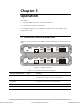
Table 3-1. Front Panel Controls and Indicators (Cont.)
Controls and Indicators Color Function
MAIN Green On when MBE is configured for local operation (applicable to
bridge mode only)
REMOTE Green On when MBE is configured for remote operation (applicable
to bridge mode only)
LAN TX Yellow On when packets are being transmitted to the LAN
RX Yellow On when packets are being received by the LAN
ERR Red On continuously when connection to LAN has failed
LINK TX Yellow On when a packet is being transmitted to the link
RX Yellow On when a packet is being received from the link
ERR Red On when discontinuity occurs in the link or if other
Communication link faults exist
3.2 Operating Instructions
GROUNDING - This unit should always be grounded through the protective
earth lead of the power cable.
Before connecting AC power to this unit, the mains plug should be inserted
only into a socket outlet provided with a protective earth contact. The
protective action must not be negated by use of an extension cord (power
cable) without a protective conductor (grounding). Interruption of the
protective (grounding) conductor (inside or outside the unit), or disconnection
of the protective earth terminal can render this unit dangerous.
Initial Setup
To begin configuring MBE:
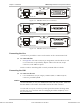
1. Connect MBE to an ASCII terminal or a PC terminal emulator.
2. Connect the CBL-RJ45/D9/F/6FT control cable, supplied with MBE, between
the RJ-45 control port on the MBE front panel, and the DB-9 connector on the
terminal.
3. Set the terminal to work at any baud rate from 4.8 to 19.2 kbps, No Parity,
8 data bits, and 1 stop bit.
It is suggested to use 9.6 kbps.
For complete configuration details, see the LAN RANger Series Configuration
Guide.
Warning
Note
Order from: Cutter Networks
Ph:727-398-5252/Fax:727-397-9610
www.bestdatasource.com