
Specifications


Appendix A Pinouts Installation and Operation Manual
A-4 MNG-ETH and USER-ETH Connector Optimux-106 Ver. 6.1
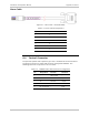
Control Cable - CBL-MUSB-DB9F
Figure
A-3. Control Cable - CBL-RJ45-DB9/F
Table
A-4. Control Cable Pin Assignment
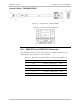
A.5 MNG-ETH and USER-ETH Connector
One LAN Ethernet RJ-45 connector is mounted on the MNG-ETH module. The
following table lists the pinout for this connector.
Table
A-5. MNG-ETH and USER-ETH RJ-45 Connector Pin Assignment
Pin Designation Function Direction
3 RX+ Receive – positive lead Input
6 RX- Receive – negative lead Input
1 TX+ Transmit – positive lead Output
2 TX- Transmit – negative lead Output
4, 5, 7, 8 – CAP to GND –