
Specifications


Installation and Operation Manual Chapter 1 Introduction
Optimux-106 Ver. 6.1 Functional Description 1-3
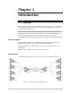
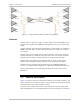
Figure
1-3 Optimux-106 Front Panel
The rear panel includes receptacles for connecting AC or DC power, four
tributary ports, two uplinks, a control port, an alarm relay port, a management
Ethernet port and a User Ethernet port (If ordered) as well as various indicator
LEDs. The Optimux-106 rear panel is fully described in
Chapter 2
.
1.3 Functional Description
Printed Circuit Boards
Optimux-106 contains the following printed circuit boards:
• Main board, including one tributary interface (with 4 RJ-45 connectors)
• One or two uplink interface boards (A and B)
• USER Ethernet port up to 75 Mbps
• One or two power supplies (A and B):
AC/DC wide-range power supply (100-240 VAC or -40 to -72 VDC)
Uplink Interface Characteristics
The fiber optic interface provides a secure link in hazardous or hostile
environments, increasing the maximum connection range, and achieving immunity
against electrical interference and protection against the harmful effects of
ground loops. The fiber optic uplink interface complies with the requirements of
ITU-T Rec. G.955, and uses a proprietary signaling format that ensures optimum
performance. To optimally meet a wide range of system requirements, the fiber
optic interface can be ordered for operation over 62.5/125 micron multimode
fibers (typical attenuation 3.5 dB/km at 850 nm), as well as over low-loss 9/125
micron single mode fibers (typical attenuation 0.4 dB/km at 1310 nm, and
0.25 dB/km at 1550 nm).
The fiber optic interface is hot swappable, allowing for quick and easy
replacement in the field.