
Specifications


Installation and Operation Manual Chapter 3 Operation
Optimux-106 Ver. 6.1 Default Settings 3-3
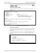
Rear Panel Indicators
Figure
3-2
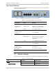
shows the typical Optimux-106 Rear panel.
Table
3-2
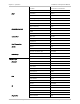
lists the functions
of the Rear panel indicators.
Figure
3-3. Optimux-106 Rear Panel – Plastic Enclosure
Table
3-2. Optimux-106 Rear Panel Indicators
LED Function Color Meaning
USER ETH: LINK/ACT Yellow On - USER link is up
(Optimux-106 ETH
version only)
Blinking yellow USER link is up and Rx and/or Tx
frames are being transmitted
Yellow Off – USER link is down
USER ETH: 100
(Optimux-106 ETH
version only)
Green On – 100M mode
Off – 10M mode
MNG ETH: LINK/ACT Yellow On - Management link is up
Blinking yellow Management link is up and Rx
and/or Tx frames are being
transmitted
Yellow Off – Management link is down
MNG. ETH: 100 Green On – 100M mode
Off – 10M mode
SIG
Located on the
bottom of the fiber
optic module
Green On – Signal is detected on fiber
optic module
Off – signal not detected
3.3 Default Settings
Table
3-3
lists the default settings of the Optimux-106 configuration parameters.
Table
3-3. Default Settings
Type Parameter Default Value
System
Device Information
Name Optimux-106