
Specifications


Installation and Operation Manual Chapter 5 Monitoring and Diagnostics
Optimux-106 Ver. 6.1 Monitoring Performance 5-3
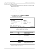
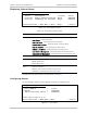
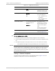
Redundancy mode The redundancy state of the system:
• AUTO
• MANUAL
• OFF
The option is hidden when redundancy status is not available.
Force Link Indicates the main uplink
Active Link Identifies the currently active link
PS A Status The state of the Power Supply A:
• OK
• Fault
PS B Status The state of the Power Supply B:
• OK
• Fault
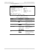
Alarm Indication Current system status:
• Normal - System is functioning normally; no alarms activated
• Major - One or more major alarms are currently activated
• Minor - One or more minor alarms are currently activated
Test Indication Indicates whether any tests are currently active in the device:
• ON - Tests are currently active in the device
• OFF - No tests are currently running
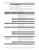
³ To set the device to monitor:
• Enter 1.
The Device Number toggles between Local and Remote, to indicate the
device currently being monitored.
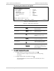
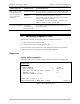
Monitoring the Interface Status of the System
The Interface Status Screen displays the current status of the local and remote
interfaces.
Optimux-106
Monitoring>System>Interface Status
Description Type Operation Speed
1 Loc uplink A Proprietary Up 101904000
2 Loc uplink B Proprietary Down 101904000
3 Loc Ch 1 T1 Up 1544000
4 Loc Ch 2 T1 Up 1544000
5 Loc Ch 3 T1 Up 1544000
6 Loc Ch 4 T1 Up 1544000
7 Loc MNG-ETH ETH Up 100000000
8 Loc USER-ETH ETH UP 100000000
>
ESC-Previous menu; !-Main Menu; &-Exit; ?-Help 1User(s)
Figure
5-3. Remote System Status Screen