
Specifications


Installation and Operation Manual Chapter 5 Monitoring and Diagnostics
Optimux-106 Ver. 6.1 Handling Alarms 5-7
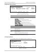
Monitoring the Status of the T1 Port
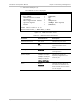
Optimux-106
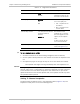
Monitoring>Physical Layer>T1
1. Device Number > (Local)
2. Port Number [1..4] > (1)
Operation > (Down)
Alarm Indication > (Signal loss)
Test Indication > (Off)
Alarm > (Unmasked)
>
Please select item <1 to 2>
ESC-Previous menu; !-Main Menu; &-Exit 1 User(s)
Figure
5-7. T1 Port Status Screen
The T1 port parameters are the same as those in the Uplink Status Screen. For
more information, see
Figure
5-6
.
³ To monitor the status of the T1 port:
1. To toggle between the local and remote device, enter 1.
The Device Number changes to identify the unit currently being
monitored (Local or Remote).
2. To select a T1 port to monitor, enter 2 and then the port number (1 to 4).
The screen displays the current status of the selected port on the
selected device.
5.2 Detecting Errors
The status of Optimux-106 is indicated by the Link A and B, CH1 to CH4 and
Power supply LEDs indicators located on the front panel. For the description of
LEDs and their functions, refer to
Chapter 3
.
5.3 Handling Alarms
Optimux-106 detects fault conditions and initiates alarms and events to alert the
user:
• Alarms (major and minor) have two statuses: ON and OFF. The alarm status
automatically changes to OFF when a fault condition that triggered the alarm
is cleared.
• Events have only ON status.