
Specifications


Appendix A Pinouts Installation and Operation Manual
A-2 Control Port Connector Optimux-108 Ver. 6.1
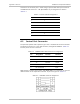
Connection of the alarm port is made using a special cable with RJ-45 connector
and DB9-female connector – CBL-RJ45-DB9/F. Its pin assignment is listed in
Table
A-1
.
Table
A-1 Alarm Cable Pin Assignment
RJ-45 DB-9
1 1
2 6
3 2
4 4
5 9
6 5
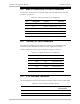
A.2 Control Port Connector
The optional Optimux-108 supervisory port has a standard RS-232 DCE interface.
The physical interface is a mini USB connector, designated CONTROL.
Table
A-2
lists the pinout for this connector.
Table
A-2. CONTROL Mini-USB Connector Pin Assignment
Pin Designation Function Direction
1 – CAP to GND –
3 RX Receive Input
2 TX Transmit Output
5 GND Ground –
4 RS-232 Enable – Input
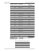
RAD supplies a special control cable, CBL-MUSB-DB9F, for connection of this mini
USB connector to the supervision terminal. Its pinout is given in
Table
A-3
.
Table
A-3. CONTROL Cable Pin Assignment