
Specifications


Installation and Operation Manual Appendix A Pinouts
Optimux-108 Ver. 6.1 V.35 Interface Connector A-3
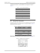
A.3 MNG-ETH and USER-ETH Port Connectors
The pinout of both Ethernet connectors (MNG-ETH and USER-ETH) is the same
and listed in
Table
A-4
.
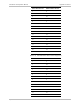
Table
A-4. Ethernet Connector Pin Assignment
Pin Designation Function Direction
3 RX+ Receive – positive lead Input
6 RX- Receive – negative lead Input
1 TX+ Transmit – positive lead Output
2 TX- Transmit – negative lead Output
4, 5, 7, 8 – CAP to GND –
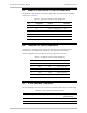
A.4 Tributary E1 Port Connectors
The tributary interface has four E1 RJ-45 connectors (for the balanced link
interface) or four dual BNC connectors (for the unbalanced interface).
The pin assignment of the E1 RJ-45 connector is given in
Table
A-5
.
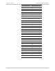
Table
A-5 E1 RJ-45 Connector Pin Assignment
Pin Designation Direction Function
1 RD(R) Input Receive Data (Ring)
2 RD(T) Input Receive Data (Tip)
4 TD(R) Output Transmit Data (Ring)
5 TD(T) Output Transmit Data Tip
3, 6, 7, 8 – – Not connected
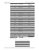
A.5 V.35 Interface Connector
The pin assignment for the V.35 Interface connector (Smart serial) is listed below.
Table
A-6. V.35 Interface Connector Pinout
Pin Number Pin Name Pin Description Type
(Input/Output)
1 TXDA Transmit data A Input
2 ETCA External clock A Input