
Specifications


Appendix A Pinouts Installation and Operation Manual
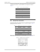
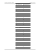
A-4 V.35 Interface Connector Optimux-108 Ver. 6.1
Pin Number Pin Name Pin Description Type
(Input/Output)
3 TXCA Transmit clock A Output
4 RXCA Receive clock A Output
5 RXDA Receive data A Output
6 DCD Data and Carrier Detect Output
7 DTR Data Terminal Ready Input
8 RTS Request To Send Input
9 RLB Remote Loopback Input
10 LLB Local Loopback Input
11 CTS Clear To Send Output
12 DSR Data Set Ready Output
13 TEST_MODE Test Mode Output
14 TXDB Transmit data B Input
15 ETCB External clock B Input
16 TXCB Transmit clock B Output
17 RXCB Receive clock B Output
18 RXDB Receive data B Output
19 NC Not connected
20 NC Not connected
21 NC Not connected
22 NC Not connected
23 NC Not connected
24 NC Not connected
25 NC Not connected
26 GND Ground GND
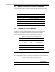
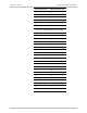
The following tables list the pinout of three interface cables CBL-AMP-DB25-TLBS,
CBL-AMP-DB25-ISO2110, and CBL-AMP-M34, which can be ordered from RAD for
connecting the V.35 connector to the Telebras DB25, ISO 2100 DB25 or M34
Interface, respectively.
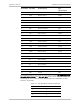
Table
A-7. CBL-AMP-DB25-TLBS Pin Assignment
Smart Serial Pin No. DB25 Telebras Pin No.
1 2
2 11
3 3