
Specifications


Optimux-108 Ver. 6.1 i
Contents
Chapter 1. Introduction
1.1 Overview.................................................................................................................... 1-1
Product Options ...................................................................................................... 1-1
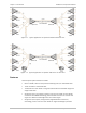
Applications ............................................................................................................ 1-1
Features ................................................................................................................. 1-2
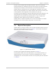
1.2 Physical Description ................................................................................................... 1-3
1.3 Functional Description ................................................................................................ 1-3
Printed Circuit Boards ............................................................................................. 1-3
Fiber Optic Uplink Interface ..................................................................................... 1-3
Technical Characteristics .................................................................................... 1-4
Uplink Redundancy Option ................................................................................. 1-4
E1 Tributary Interface ............................................................................................. 1-5
V.35 User Port ........................................................................................................ 1-5
Ethernet User Port .................................................................................................. 1-5
Timing .................................................................................................................... 1-5
Test and Diagnostics Capabilities ............................................................................ 1-6
Alarms and Alarm Indications .................................................................................. 1-7
Uplink and Triburaties ........................................................................................ 1-7
V.35 User Port .................................................................................................... 1-7
Response to Alarm Conditions ............................................................................ 1-7
Rear Panel Alarm Connector ............................................................................... 1-7
Events .................................................................................................................... 1-8
Management .......................................................................................................... 1-8
Power ..................................................................................................................... 1-8
1.4 Technical Specifications .............................................................................................. 1-8
Chapter 2. Installation and Setup
2.1 Site Requirements and Prerequisites .......................................................................... 2-1
2.2 Package Contents ...................................................................................................... 2-2
2.3 Required Equipment ................................................................................................... 2-2
2.4 Mounting the Unit ...................................................................................................... 2-2
2.5 Connecting the Interfaces .......................................................................................... 2-3
Connector Location ................................................................................................. 2-3
Connecting the Uplink ............................................................................................. 2-4
Connecting the Tributary Interface .......................................................................... 2-5
Connecting the V.35 Interface ................................................................................. 2-5
Connecting the User Ethernet Port .......................................................................... 2-6
Alarm Connector ..................................................................................................... 2-7
Connecting the Ethernet Management Port ............................................................. 2-7
Connecting the Control Port .................................................................................... 2-7
2.6 Connecting to Power .................................................................................................. 2-8
Connecting AC Power .............................................................................................. 2-8
Connecting DC Power .............................................................................................. 2-8
Chapter 3. Operation
3.1 Turning On the Unit ................................................................................................... 3-1
3.2 Indicators .................................................................................................................. 3-1
Front Panel Indicators ............................................................................................. 3-1