
Specifications


Installation and Operation Manual Chapter 1 Introduction
Optimux-108 Ver. 6.1 Physical Description 1-3
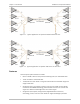
The unit can be ordered with two uplink interfaces, where the second link
interface operates as a backup for the main link. The user can select automatic
switching to the backup or manual selection of the desired link interface.
Optimux-108 has comprehensive test and diagnostics capabilities that include
local and remote loopbacks on the uplink interface and on each E1 tributary link.
A local loopback is also supported on the optional V.35 user port.
To facilitate system diagnostics, Optimux-108 features LED status indicators, AIS
alarm generation and recognition, and dry contact closure upon link failure.
Optimux-108 can be powered from 100-240 VAC or –40 to -72 VDC. Two
independent power supplies can be installed, for redundancy.
Optimux-108 is a compact standalone unit. A rack mount adapter kit enables
installation of one or two (side-by-side) units in a 19-inch rack.
1.2 Physical Description
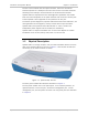
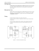
Optimux-108 is a 1U high, compact, easy-to-install standalone device. The front
view of the Optimux-108 unit is shown in
Figure
1-3
. The location of LEDs and
connectors on the metal enclosure is similar.
Figure
1-3. Optimux-108, 3D View
The front panel includes LED indicators described in C
hapter 3.
The rear panel includes one or two uplink ports, 4 x E1 tributary interface, an
optional Ethernet or V.35 user port, an Ethernet management port, a serial
management port, and the power connector. The rear panel ports are described
in
Chapter 2
.