
Specifications


Installation and Operation Manual Chapter 1 Introduction
Optimux-108 Ver. 6.1 Functional Description 1-5
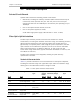
1550/1310
Transmit/Receive
9/125 single mode
Single fiber
Laser WDM
[SF2]
-12 -34 47 29.2 SC
1550 9/125 single mode Laser -12 -34 76
47.2
ST, SC, FC/PC
1550 9/125 single mode Laser
[long haul]
-2 -34 120
74.5
ST, SC, FC/PC
* The Receiver Sensitivity for units with the Ethernet port is 32 dBm.
All fiber optic interface options offer high performance and have a wide dynamic
range.
The SF3 option uses an SC/APC connector. The FO cable connected to it must
therefore be of the same type.
Uplink Redundancy Option
Optimux-108 can be ordered with one or two link interface options. Each
interface operates independently, and can be ordered from the link options listed
above.
In the uplink redundancy option, Optimux-108 supports fully automatic switching
between the main and the backup link. The main link has priority, therefore
normally it is selected for use, and the backup link is disabled. In case a failure
occurs on the main link, Optimux-108 automatically switches to the backup link
and continues providing normal service. After the main link returns to normal
operation, it is automatically reselected.
Each link interface has its own set of indicators that display the current state of
the link.
E1 Tributary Interface
The Optimux-108 tributary interfaces meet the requirements of ITU-T Rec. G.703.
The tributary ports (1-4) can be one of the following:
• 120Ω balanced line interface, terminated in a RJ-45 8-pin connector
• 75Ω unbalanced interface, terminated in two BNC coaxial connectors.
Line coding is HDB3. The nominal balanced interface transmit level is ±3V, and the
unbalanced interface transmit level is ±2.37V. The maximum line attenuation is up
to 6 dB, and each E1 signal is processed by an adaptive equalizer that
compensates for various cable lengths to ensure optimal performance. Phase
locked loops (PLL) are used to recover the clock signals, and the resulting jitter
performance complies with the requirements of ITU-T Rec. G.823.
Each tributary interface has its own set of indicators that show the current state
of the tributary link. The user can disable the alarm indications generated by
unused interfaces. AIS data streams are transmitted instead of failed or
unconnected tributary data streams.
Note