
Specifications

Installation and Operation Manual Chapter 1 Introduction
Optimux-108 Ver. 6.1 Technical Specifications 1-11
Diagnostics
Local and remote loopbacks on uplink and on each
E1 tributary link
Local loopback on optional V.35 user port
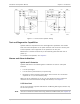
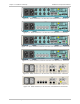
Indicators
Front Panel
PWR
On (green): both power supplies OK
On (red): power supply A fault
On (yellow): power supply B fault
Off: power supply fault
LINK A/B
On (red): Sync/Signal Loss on Link A/B
On (yellow): not used
Off: normal operation
CH1 to CH4
On (red): Signal Loss on channel
On (yellow): AIS received on channel
Off: normal operation
Rear Panel
Sig Link A/B (on the
fiber optic module)
On (green): signal exists on Link A/B
Off: no signal on Link A/B
LINK/ACT
On (yellow): link is up
Off: link is down
Blinks: frames are transmitted
100
On (green): 100 Mbps mode
Off: 10 Mbps mode
Alarm Relay
Connector
Shielded RJ-45
Contact Functions
Set of floating normally-closed/normally open
contacts for major and minor alarm indication
Contact Rating
Maximum 0.5A (at 30 VDC or 30 VAC) through
closed contacts
Power
Wide range AC/DC
Power Supply
100 to 240 VAC, 50 or 60 Hz, 25 VA
-48/60 VDC (-40 to-72 VDC), 9W
Physical
Plastic Enclosure
Height
4.37 cm / 1.7 in (1U)
Width
21.7 cm /8.5 in
Depth
17.0 cm / 6.7 in
Weight
0.5 kg / 1.1 lb