
Specifications


Installation and Operation Manual Chapter 2 Installation and Setup
Optimux-108 Ver. 6.1 Connecting the Interfaces 2-3
2.5 Connecting the Interfaces
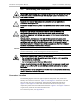
Eye damage may be caused by a broken or unterminated fiber optic or connector
if the laser beam is viewed directly or with improper optical instruments. The
laser beam is invisible.
Access to the inside of the equipment is permitted only to qualified and
authorized service personnel.
Disconnect the unit from the power line and from all the cables before removing
cover.
Dangerous high voltages are present inside the Optimux-108 when it is
connected to power and/or to the links. Moreover, under external fault
conditions, dangerous high voltages may appear on the lines connected to the
Optimux-108.
Any adjustment, maintenance, and repair of the opened instrument under
voltage should be avoided as much as possible and, when inevitable, would be
carried out only by a skilled technician who is aware of the hazard involved.
Capacitors inside the instrument may still be charged even after the instrument
has been disconnected from its source of supply.
Optimux-108 contains components sensitive to electrostatic discharge (ESD). To
prevent ESD damage, avoid touching the internal components.
Optimux-108 includes Class 1 lasers. For your safety:
• Do not look directly into the optical connectors while the unit is operating.
The laser beams are invisible.
• Do not attempt to adjust the laser drive current.
The use of optical instruments with this product will increase eye hazard. Laser
power up to 1 mW at 1300 nm and 1550 nm could be collected by an optical
instrument.
Use of controls or performing procedures other than those specified herein may
result in hazardous radiation exposure.
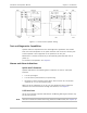
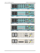
Connector Location
The following figures show two typical Optimux-108 plastic rear panels and
identify the connector locations.
Figure
2-1
and
Figure
2-2
show the unit with
the V.35 user port and, respectively, balanced and unbalanced tributaries.
Figure
2-3
and
Figure
2-4
show the unit with the Ethernet user port and,
respectively, balanced and unbalanced tributaries.
Figure
2-5
to
Figure
2-8
show
a typical rear panels of the metal enclosure unit.
For connector pinout, see
Appendix A
.
Warning
Warning
Warning
Caution
Warning