
Specifications


Installation and Operation Manual Chapter 2 Installation and Setup
Optimux-108 Ver. 6.1 Connecting the Interfaces 2-7
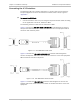
Figure
2-11. CBL-AMP-M34 Cable
Connecting the User Ethernet Port
The user Ethernet port interface terminates in an 8-pin RJ-45 connector.
³ To connect the User Ethernet Port:
• Connect the Ethernet user equipment to the MNG-ETH connector using a
UTP-CAT5 cable.
Alarm Connector
This connector connects the changeover contacts of the major (optinally, minor)
alarm relays to the external equipment. Connection of the alarm port is made
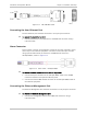
using a special cable with RJ-45 connector and DB9-female connector –
CBL-RJ45-DB9/F, shown in
Figure
2-12
.
Figure
2-12. Alarm Cable - CBL-RJ45-DB9/F
³ To connect the alarm connector to the external equipment:
1. Connect the RJ-45 connector of the CBL-RJ45-DB9/F cable to the ALARM
connector located on the Optimux-108 rear panel.
2. Connect the external DB9-female connector of the CBL-RJ45-DB9/F cable to
the external equipment.
Connecting the Ethernet Management Port
The Ethernet Management Port interface terminates in an 8-pin RJ-45 connector.
³ To connect the Ethernet Management port:
• Connect the management station to the MNG-ETH connector using a
UTP-CAT5 cable.