
Specifications
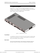

Optimux-XLT1 Installation and Operation Manual Chapter 1 Introduction
Functional Description 1-9
DTE DCE OP
INTEXTLBT
DTEDCE OP
TXC
RXC
TXD
RXD
MUX
OSC
TXC
RXC
TXD
RXD
MUX
OSC
TXD
TXD
TXC
TXC
RXD
RXD
RXC
RXC
EXTC
EXTC
TXD
TXC
RXC
EXTC
RXD
TXC
EXTC
TXD
RXC
RXD
DCEDCE
TXD
RXC
EXTC
TXC
RXD
TXD
TXC
RXC
EXTC
RXD
V35/RS530 V35/RS530
EXTEXTEXT
Not
Used
Cross Cable
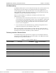
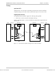
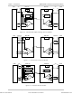
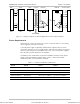
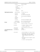
Figure 1-7. Timing Description for Tail End Application with V35/RS530 Module
Power Requirements
Optimux-XLT1 can be connected to 115 VAC or 220 VAC mains, or to a battery
source supplying -48 VDC or 24 VDC.
A second power supply is optionally installed in the Optimux-XLT1 to assure
continuous operation in case of supply failure. When the two supplies are turned
ON, they share the power consumption of the unit. If one of the power supplies
fails, the other provides full power consumption.
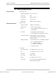
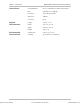
A limitation in the combination of interface installation exists due to the power
supply currently installed in Optimux-XLE1. Table 1-3 shows the feasible
combinations that can be ordered or installed.
Table 1-3. Interface Installation Combinations
Port A Port B Port C Port D
Ethernet (10BaseT) 4HS/V35 4T1 or 2T1 or 10BaseT 4T1 or 2T1 or 10BaseT
Ethernet (10BaseT) 4HS/RS530 or 4HS/X21 4HS/RS530 or 4HS/X21 4HS/RS530 or 4HS/X21
Ethernet (10BaseT) 4T1 or 2T1 or 10BaseT 4T1 or 2T1 or 10BaseT 4T1 or 2T1 or 10BaseT
Ethernet (10BaseT) Fast Ethernet 4T1 or 2T1 or 10BaseT 4T1 or 2T1 or 10BaseT
Ethernet (10BaseT) Fast Ethernet Fast Ethernet 4T1 or 2T1 or 10BaseT
Order from: Cutter Networks
Ph:727-398-5252/Fax:727-397-9610
www.bestdatasource.com