
Specifications

Chapter 2 Installation and Setup Optimux-XLT1 Installation and Operation Manual
2-2 Installation and Setup
2.3 Package Contents
A preliminary inspection of the equipment contained in the shipping box should
be made before unpacking. Evidence of damage should be noted and reported
immediately. The Optimux-XLT1 package includes the following items:
• Optimux-XLT1 unit
• Optimux-XLT1 Installation and Operation Manual
• Power cable – 110 or 220 depending on your order
• Interface adapter cable – High speed modules depending on your order
• If –48 VDC version is ordered, 48V plug is supplied
• If 24 VDC version is ordered, 24V plug is supplied.
2.4 Installation and Setup
This section details the functions and positions of the internal switches and
jumpers used to configure the Optimux-XLT1 unit for your particular application.
A common configuration procedure is provided. Then, the configuration options
and the default settings for each module are detailed.
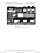
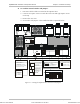
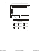
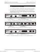
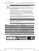
Identifying Optimux-XLT1 Modules
Figure 2-1 and shows the modular construction of the Optimux-XLT1 unit. Use this
figure to identify the modules supplied.
➤ To remove the unit from its case:
1. Unscrew three captive screws on each side of the unit and eight captive screws
on the top.
2. Remove the Optimux-XLT1 top cover.
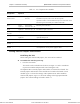
3. Check that the optional modules ordered are installed in the unit case. Refer
to Table 2-1 and verify the designation of the modules/cards in capital letters.
Order from: Cutter Networks
Ph:727-398-5252/Fax:727-397-9610
www.bestdatasource.com