
Specifications

Chapter 2 Installation and Setup Optimux-XLT1 Installation and Operation Manual
2-4 Installation and Setup
Table 2-1. List of Optimux-XLT1 Modules
Module
Designation
Fixed/
Optional
Location Used to provide
Main Board/
OPTI-T1/LAN
Fixed Along the width of
the unit
Optimux-XLT1 unit control functions.
Fixed Ethernet port (section A on the front panel).
Operation modes of the fixed Ethernet port (see ETH-TOP card).
Ethernet agent functionality (see AGENT-ETH card).
ETH Fixed/
Optional
Front fixed A
Front slots B, C, D
Ethernet port connection
FETH Optional Front slots B, C, D Fast Ethernet port connection
4 T1 balanced–
4T1 BAL
Optional Front slots B, C, D ITU-T G.703 interface for four T1 balanced ports
fiber optic Link–FO Fixed/
Optional
Rear slots LINK A/B Fiber optic interface to the link. A is the main link and B is the
optional backup link.
H.S. Optional Front slots B, C, D V35/RS530/X21 Interface ports
Power supply–
PWR-A
Fixed On the rear side Optimux-XLT1 supply voltages
Power supply–
PWR-B
Optional On the rear side Power supply redundancy - power consumption sharing or full
consumption in case of power supply A failure.
Setting Internal Jumpers and Switches
Initializing the Unit
Before setting the switches and jumpers, the unit must be initialized.
➤ To initialize the unit after power up:
• Press the reset switch.
The switch can be reached from the front (see Figure 3-1) with a screwdriver
(to prevent unauthorized personnel from resetting the unit).
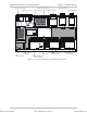
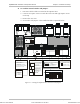
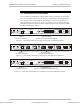
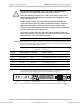
The Optimux-XLT1 internal jumpers and switches are located on its board. The
internal jumpers and switches of the modules are located on the board of each
module. Figure 2-2 shows the settings of the Optimux-XLT1 and its modules’
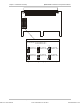
switches and jumpers. Figure 2-3 shows the settings of the high-speed module
jumpers. The internal settings are listed in Table 2-2.
Order from: Cutter Networks
Ph:727-398-5252/Fax:727-397-9610
www.bestdatasource.com