
Specifications

Chapter 2 Installation and Setup Optimux-XLT1 Installation and Operation Manual
2-8 Installation and Setup
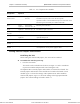
Table 2-2. Internal Settings (Cont.)
Identification of
Internal Setting
Function Settings Factory Setting
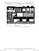
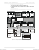
T1 Channel Modules
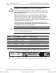
SW1
Sections 1–4 On the T1 modules are used to
enable T1 interface alarms to the
Optimux-XLT1 system control
Sections 3–4 are not used in the
2T1/BAL channel modules
ON – Alarms enabled
OFF – Alarms disabled
ON
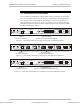
SW2
Sections 1–3 On the T1 modules are used to set
the line length equalizer that
determines the shape and
amplitude of the transmit pulse.
Sections 4 are not used and always
set to OFF.
ON, ON, OFF – 0–133 ft
OFF, OFF, ON – 133–266 ft
ON, OFF, ON – 266–399 ft
OFF, ON, ON – 399–533 ft
ON, ON, ON – 533–655 ft
ON, ON, OFF
JP1 Determines the line code
implemented by the T1 interface
B8ZS – Line code set to B8ZS
AMI – Line code set to AMI
B8ZS
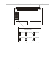
High Speed Module
JP1, JP2 Select timing mode for channels 1
and 2
LBT – Loopback timing
INT – Internal timing
EXT – External timing
INT
JP4, JP5 Select timing mode for channels 3
and 4
LBT – Loopback timing
INT – Internal timing
EXT – External timing
INT
Order from: Cutter Networks
Ph:727-398-5252/Fax:727-397-9610
www.bestdatasource.com